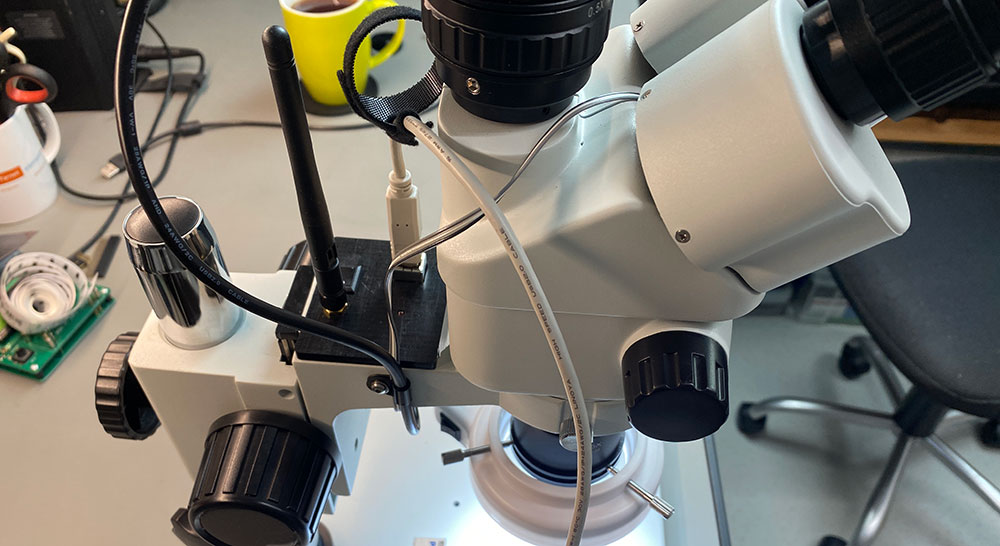
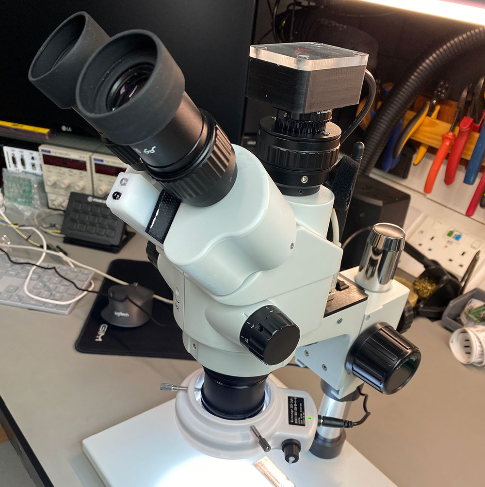
Since adding the Raspberry Pi High-Quality Camera to our microscope we have been using OBS Studio to capture video from the microscope along with our Canon DSL via an Elgato Cam Link 4K for desktop recording.
When using the microscope, we have been using an Elgato Streamdeck to switch between the different video sources in OBS.
Sometimes when working on projects under the microscope we would forget to switch the OBS camera and so we missed recording the items we were working on. To resolve this, we decided to add an automatic switching system to the microscope so it would switch to the correct scene in OBS to record the microscope camera when being used.
The initial plan was to add a switch onto the microscope body and find a way to link this to the PC to trigger the scene change but this would also have the same issues as the Streamdeck.
Websockets and OBS
OBS Studio has many plugins to expand the software and we found a remote control plugin via network WebSockets called "Websockets plugin" which allows remote control via the network.
With the WebSockets plugin installed in OBS, we wrote a demo application which would send commands to the recording computer allowing us to switch scenes.
Sensors and Wi-Fi Module
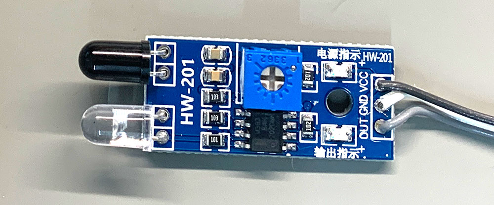
To detect someone using the microscope we decided to use an IR Infrared Obstacle Avoidance Sensor Module from Amazon which has a digital output and could be connected to a Wi-Fi module and communicate with OBS via the Wi-Fi connection to the wired network.
Previously we had to use Espressif Systems ESP8266 Wi-Fi modules but for this project, we decided to try a different more powerful Wi-Fi module from Espressif, the ESP32-WROOM-32UE(M113EH2800UH3Q0) which is an ESP32 ECO V3, with 16 MB SPI flash and an IPEX antenna connector allowing the use of an external antenna.
The ESP32 modules have many more I/O pins than the more basic ESP8266 modules and as the microscope is used in our loft workshop having the external antenna would give a better Wi-Fi signal than the small PCB antenna on the ESP8266 board.
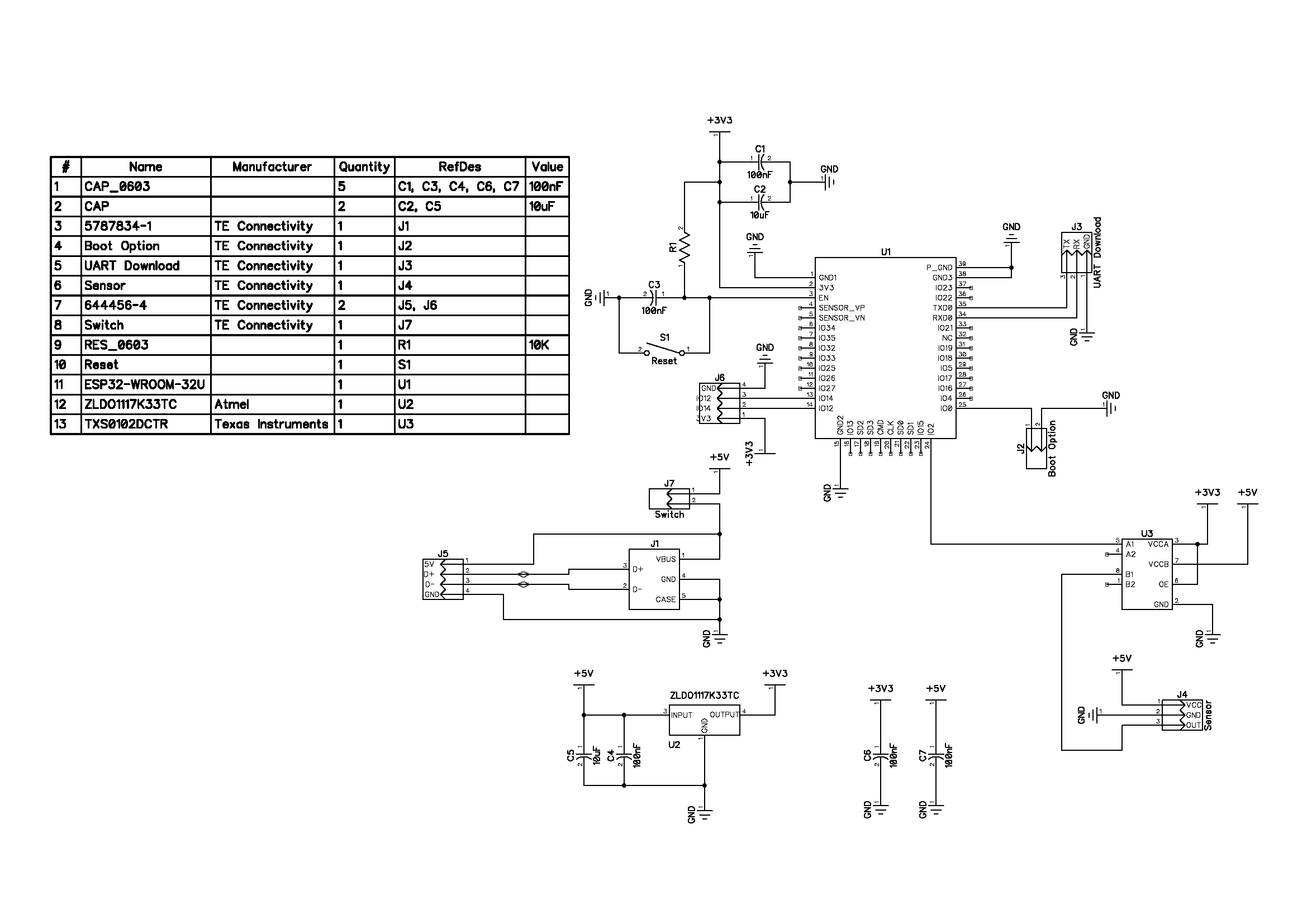
The Circuit
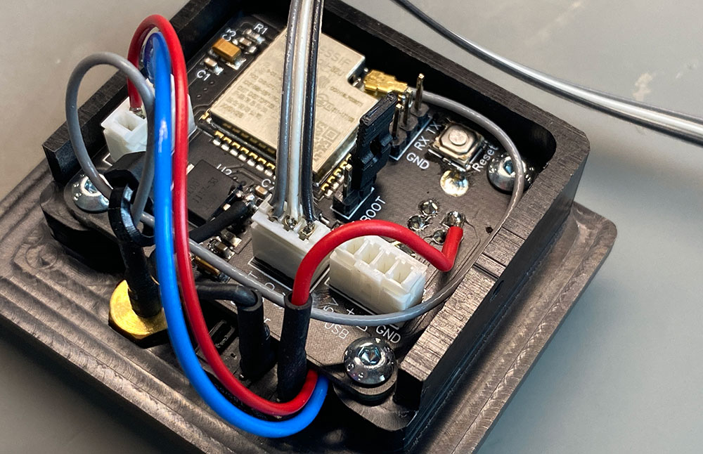
The circuit contains the ESP32 module, a 3.3V power regulator and a logic level shifter. The proximity sensor module can run from 3.3V but after experimenting with the module we found that the range of the LED and the photoelectric sensor was not good enough at 3.3V to work effectively so we decided to run the sensor at 5V and use a level shifter to drop the 5V down to 3.3V to work with the ESP32 module.
A USB socket is soldered onto the PCB with the USB power and signal wires passed through to a 4-pin header which connects to the camera on the microscope. This allows the circuit to be powered from the same USB cable as the camera. The PCB files can be downloaded from GitHub, link below.
Building the enclosures
Andrew designed a small PCB which includes the ESP32 module, power regulation, a USB socket and connectors for the sensor, USB pass-through, an expansion header and a programming header.
The PCB was designed to fit into a small open space at the rear of the microscope. A custom case was designed using Fusion 360 and cut on our CNC milling machine from a piece of acetal plastic.
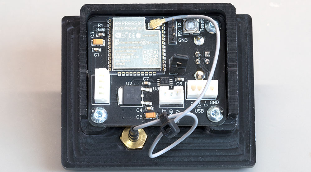
The case also holds a toggle switch to switch the device on and off and a status LED which lights when a Wi-Fi and WebSocket connection has been established. The power toggle switch was not originally designed into the PCB layout, so a small modification was made by cutting the power trace on the PCB and soldering the switch between the USB socket and voltage regulator. The PCB design has since been updated to include a socket for the power switch.
The IR sensors are supplied as a small PCB with the LED emitter and receiver at one end and a three-pin connector at the other. The centre of the PCB contains a comparator circuit and a small adjustable variable resistor to change the sensitivity of the sensor.
A small enclosure was designed for the sensor using Fusion 360 and cut on our CNC milling machine from an offcut of 6mm frosted acrylic sheet and held together with a single 2.5mm bolt.
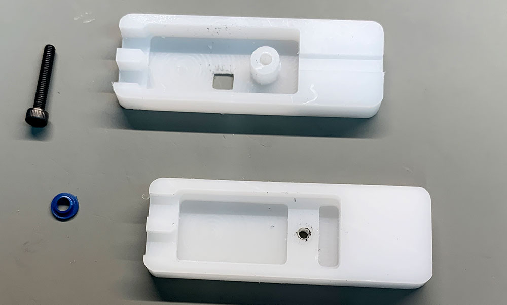
The sensor enclosure was fitted to the microscope eyepieces using Velcro double-sided tape and the sensitivity was adjusted to trigger when the user's face was close to the microscope.
Firmware
The firmware to run on the ESP32 module was written using VS Code with the Platform IO plugin installed.
The program flow is fairly simple. On start-up the GPIO is set up for the input and LED pins, the Wi-Fi connection is established and the ESP32 creates a web socket to a computer running OBS. An LED is used to signal when a successful Wi-Fi and WebSocket connection has been established.
The main program loop monitors the input pin which is connected to the proximity sensor. The sensor pulls the input low when active which sends a request to OBS to change the scene to a pre-set target. When the proximity sensor is deactivated, a request is sent to set OBS back to the previous scene. This allows you to change scenes in OBS and the firmware will automatically pick the correct scene when switching away from the microscope camera.
The firmware includes variables for setting the Wi-Fi SSID, password and IP address. Configuration for the OBS WebSocket connection can be found in the OBS struct where you can set the target IP address, port, password and the target scene which OBS will switch to when the proximity sensor is active.
OBS Configuration
The installer for the WebSocket API for OBS studio can be downloaded and installed from https://github.com/Palakis/obs-websocket
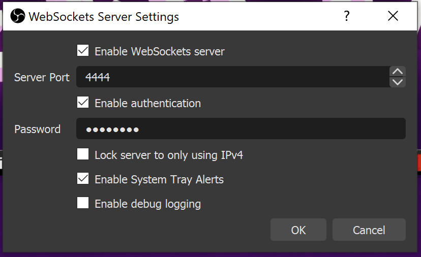
Once the plugin is installed, open OBS and you will be prompted to set a password for obs-websocket as shown below:
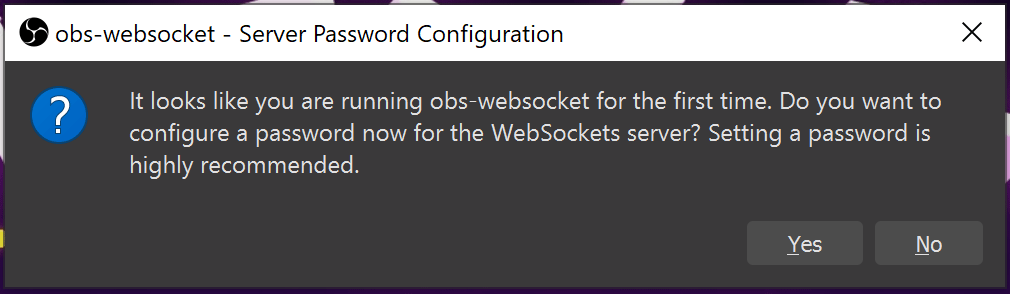
Clicking the Yes button will load the following dialog with a tick box for Enable authentication and a password field. Enter your new password and click the OK button to confirm.
Downloads
The files and code for this project can be downloaded from GitHub at https://github.com/briandorey/esp32-obs-switcher

Comments