We previously tore down several Amazon Echo devices including the 3rd gen Dot, 3rd gen Dot with Clock, the Flex, and the Echo Input. In this teardown, we will look at the new Echo Dot 4th generation model which is a smart speaker with the Amazon Alexa service.
The 4th generation Echo Dot is a new model announced in September 2020 and released in the autumn, the new design has a round appearance and buttons on the side of the curved section.
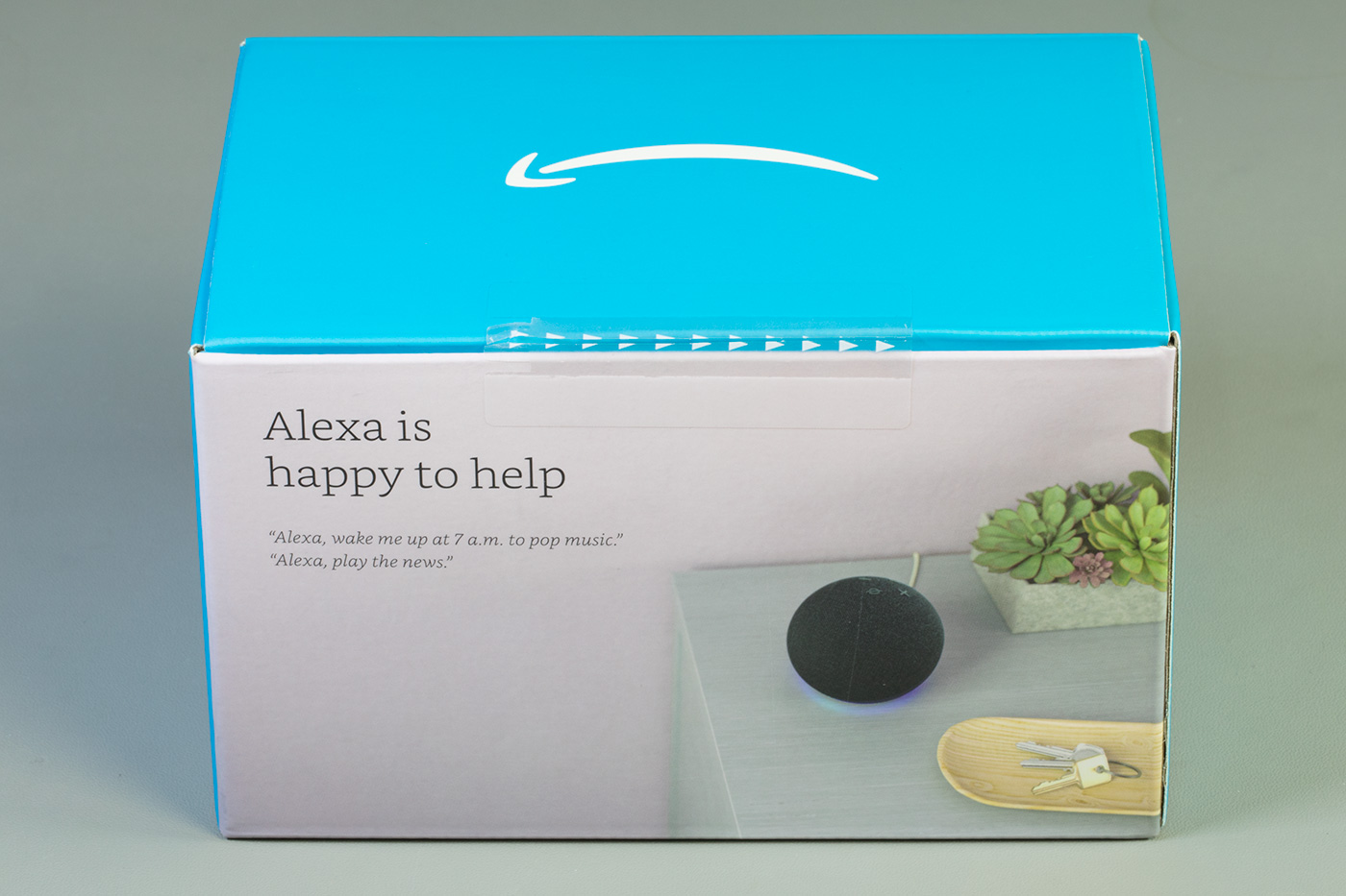
In the Box
- The Echo Dot
- 240V UK power supply
- Things to try leaflet
- Setup instructions
- Echo Dot terms of use
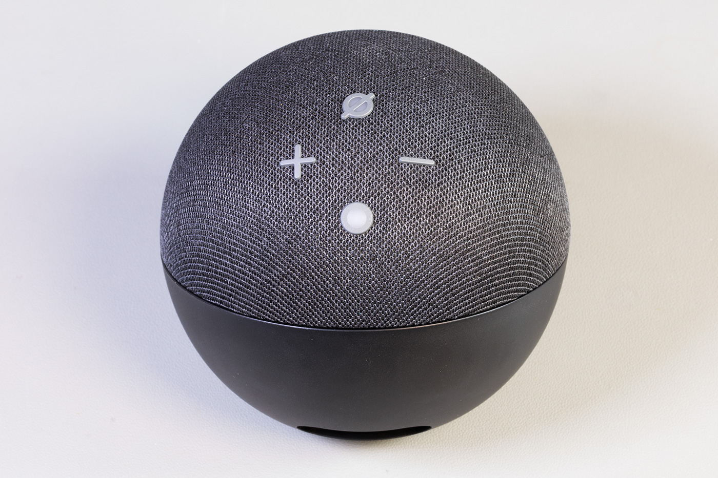
Top of the Echo Dot
The top of the smart speaker has four buttons, four microphones and an LED ring. The + and – buttons control the volume; the circle button activates Alexa and the circle with a line through it enables or disables the microphones.
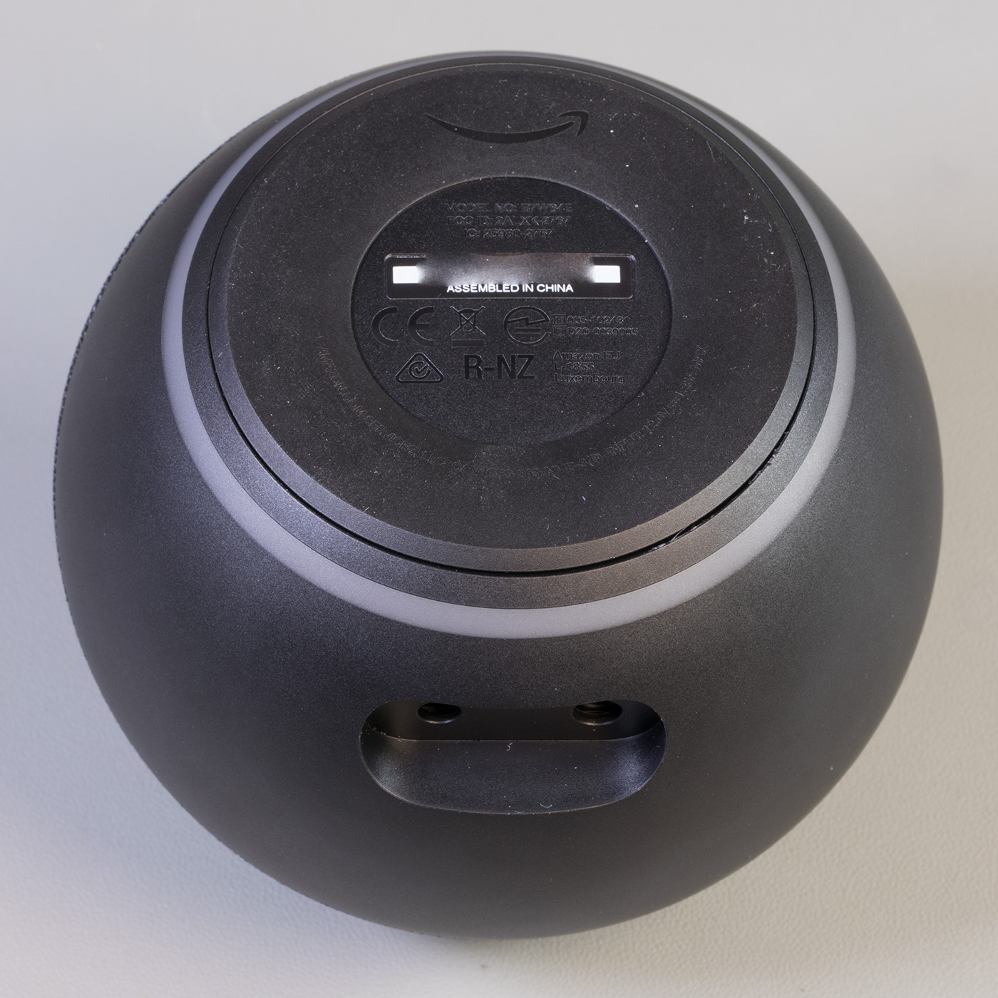
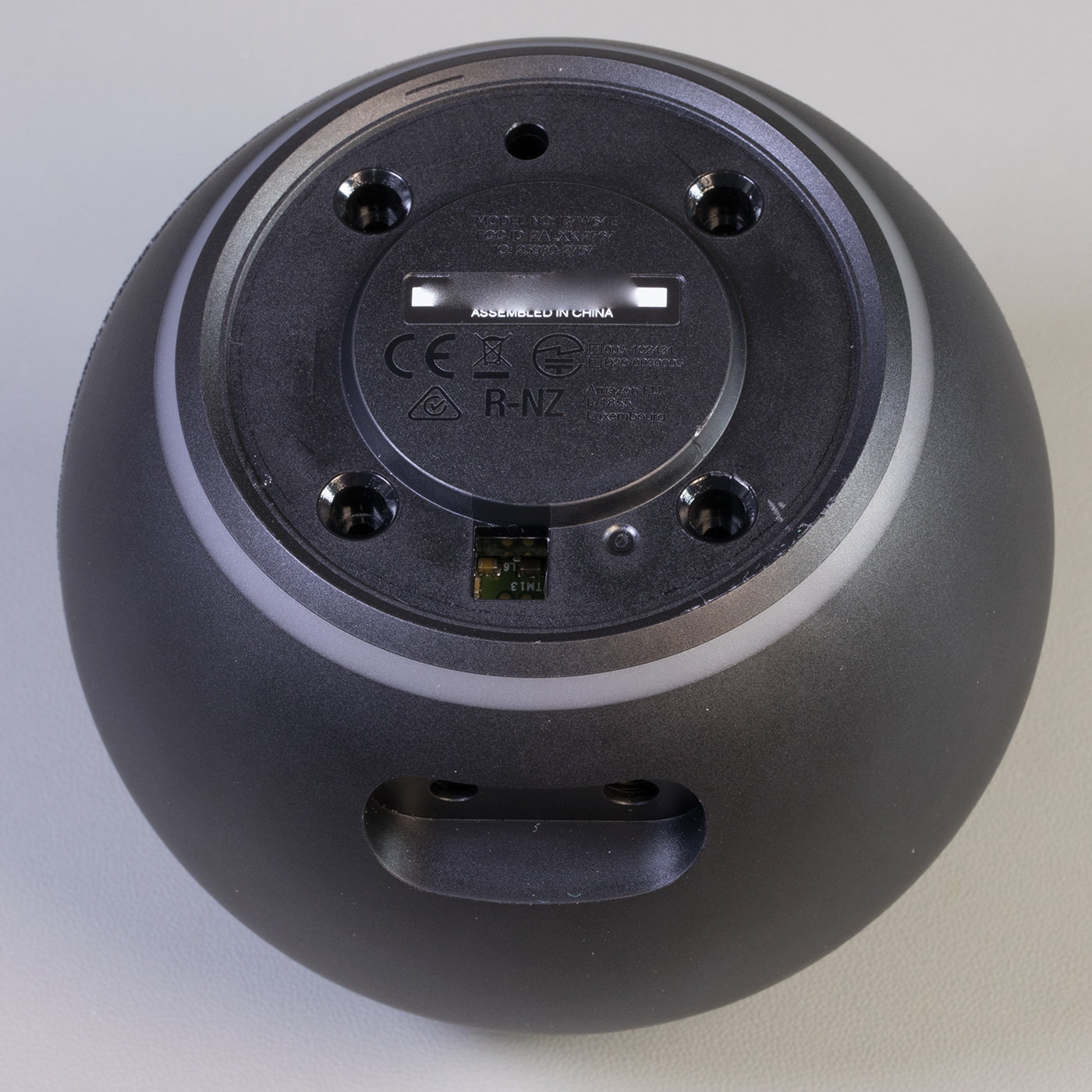
Case Base
The base has the serial number, product logos and certification marks.
On the side are a power input socket and headphone/audio out 3.5mm stereo socket.
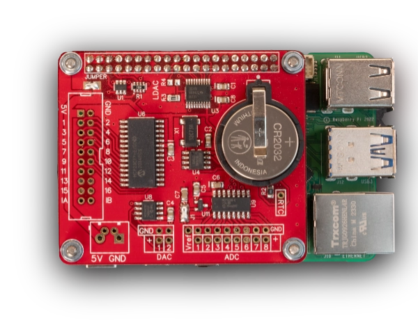
Your Raspberry Pi Projects Start Here
Please support the blog and our projects by buying your Raspberry Pi development boards and accessories from our online store at AB Electronics UK.
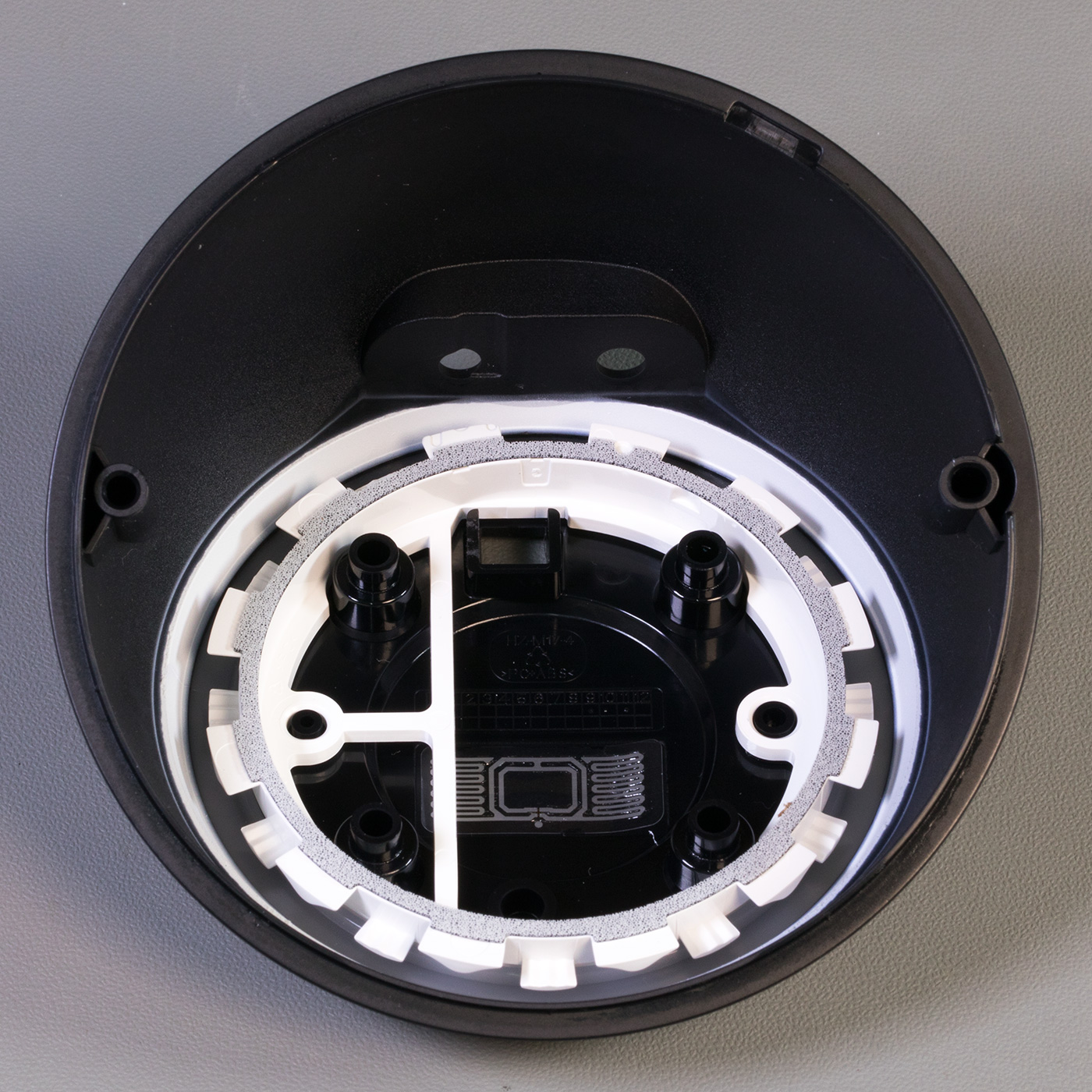
Opening the Case
The cover is held in place using adhesive tape and locator pins.
To open the case first you need to remove the non-slip rubber cover on the base of the echo dot, using a thin knife or some other flat-bladed tool.
Under the cover, you will find four T5 Torx bolts and a recessed six-pin header which appears to be a debug or programming port.
Removing the four T5 Torx bolts allows you to separate the two halves of the case.
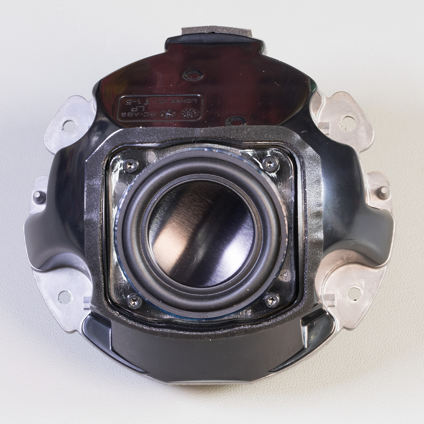
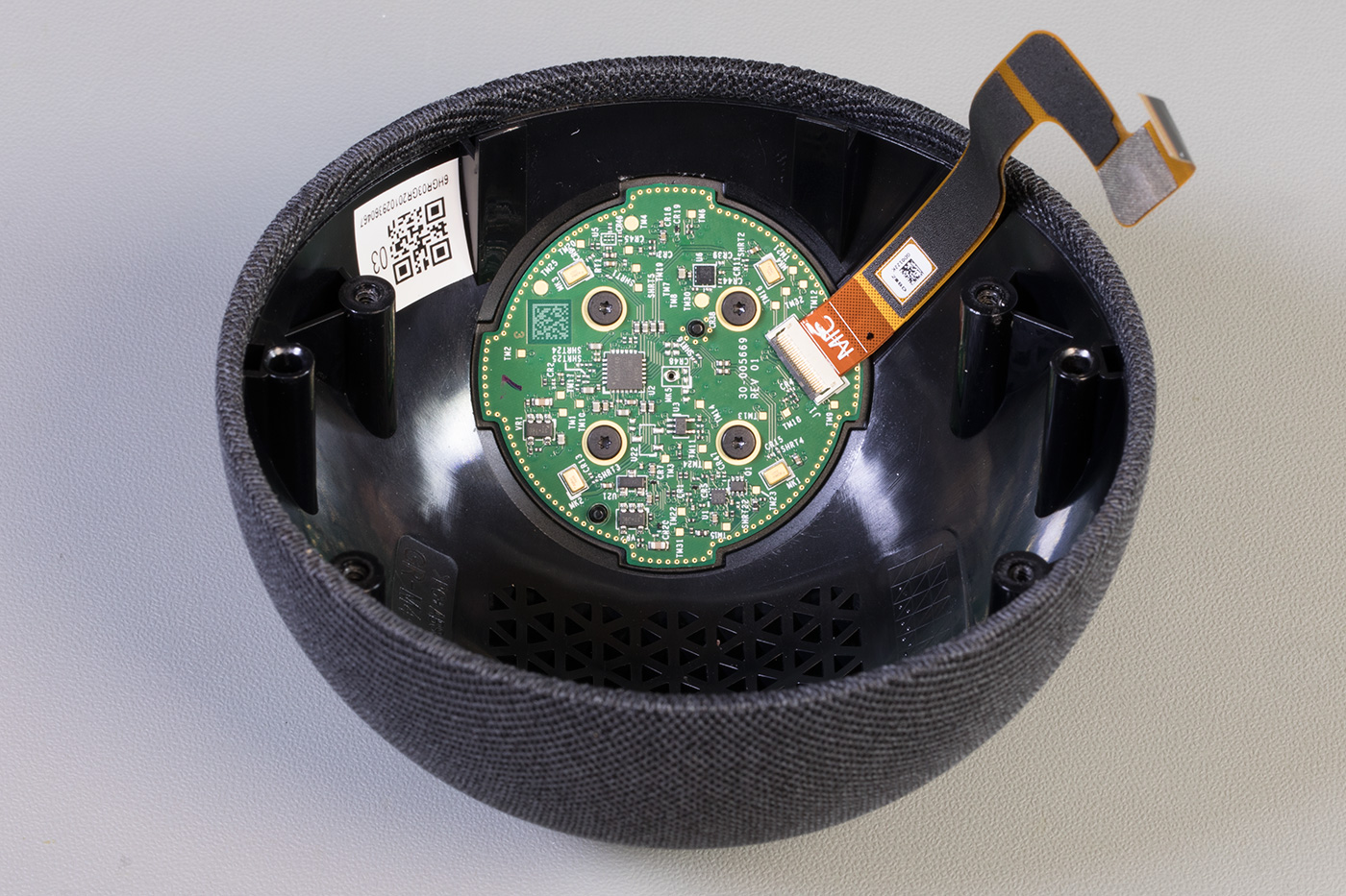
Metal Chassis with Processor PCB
Inside you will find a circuit board mounted to a cast metal housing with a small ribbon cable leading to the switch PCB.
The PCB is removed using four Torx bolts and the removal of a small flat-flex cable.
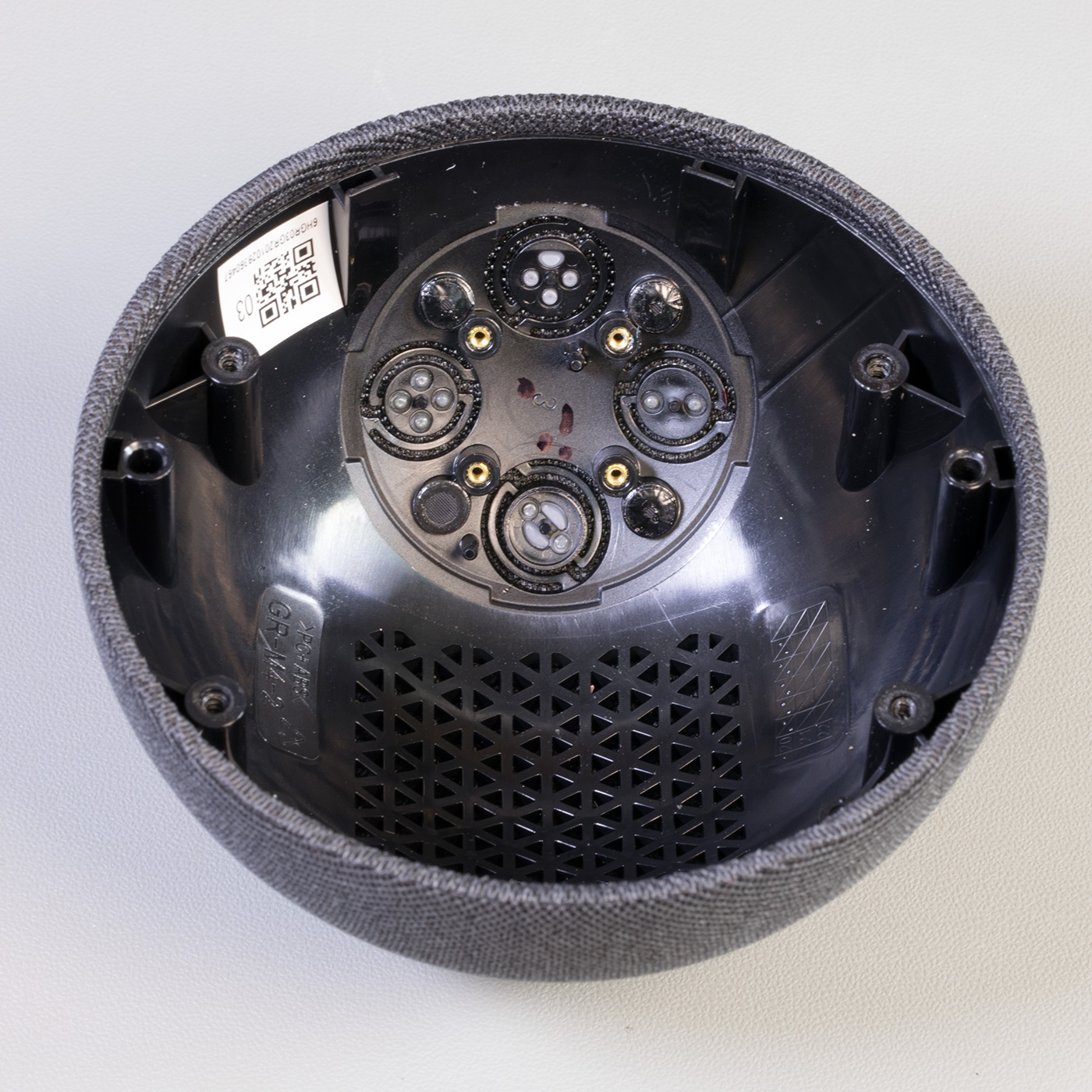
With the PCB removed the four silver Torx screws can be removed which allows the metal housing to be removed from the top cover. This reveals the switch PCB and speaker.

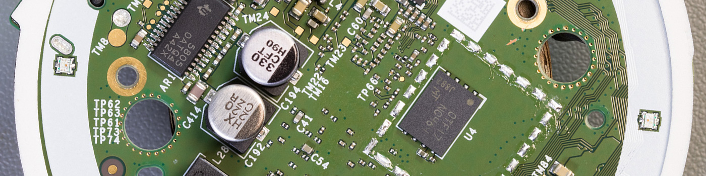
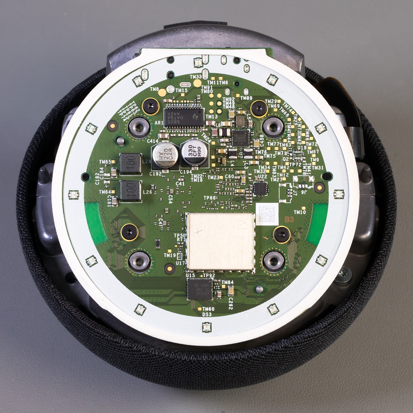
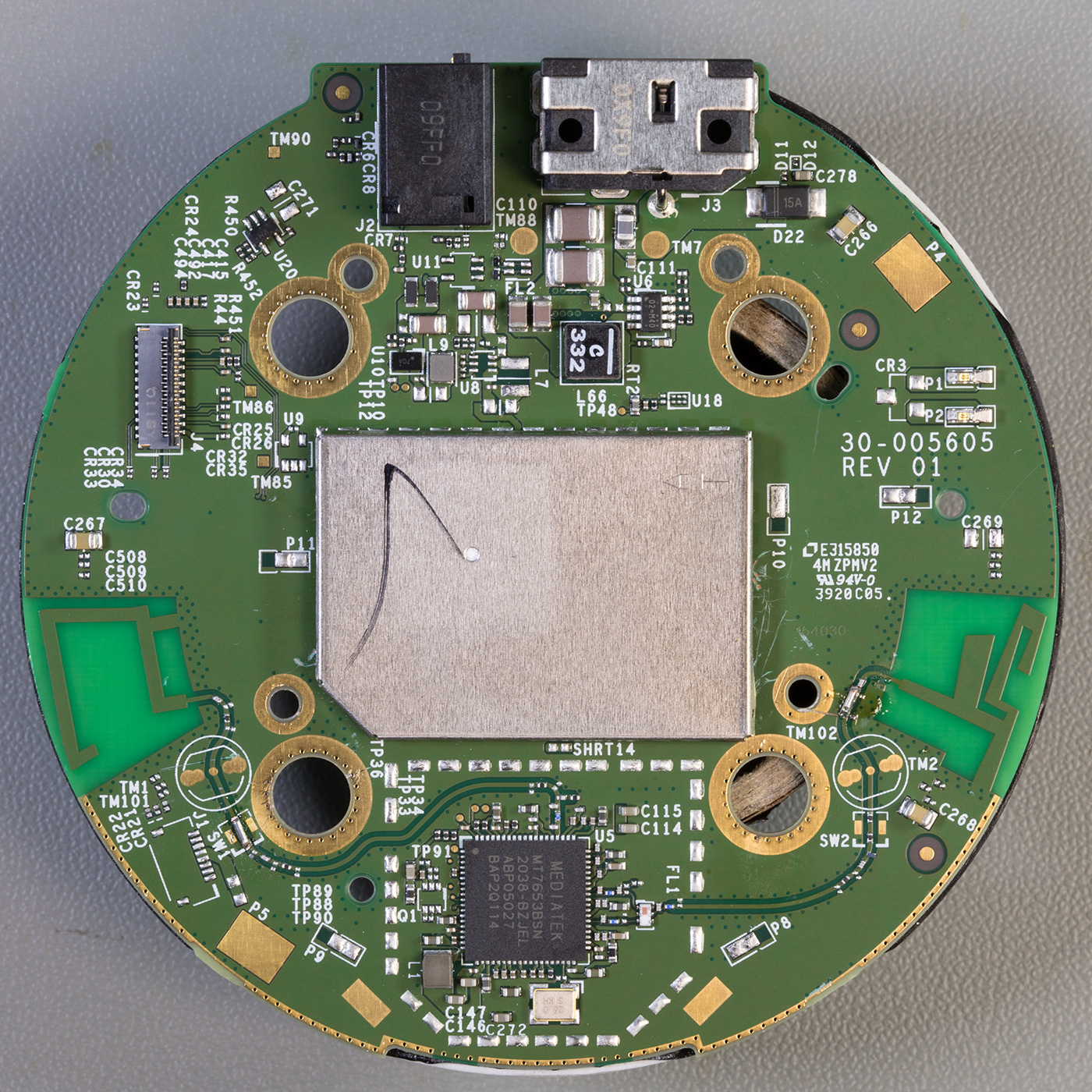
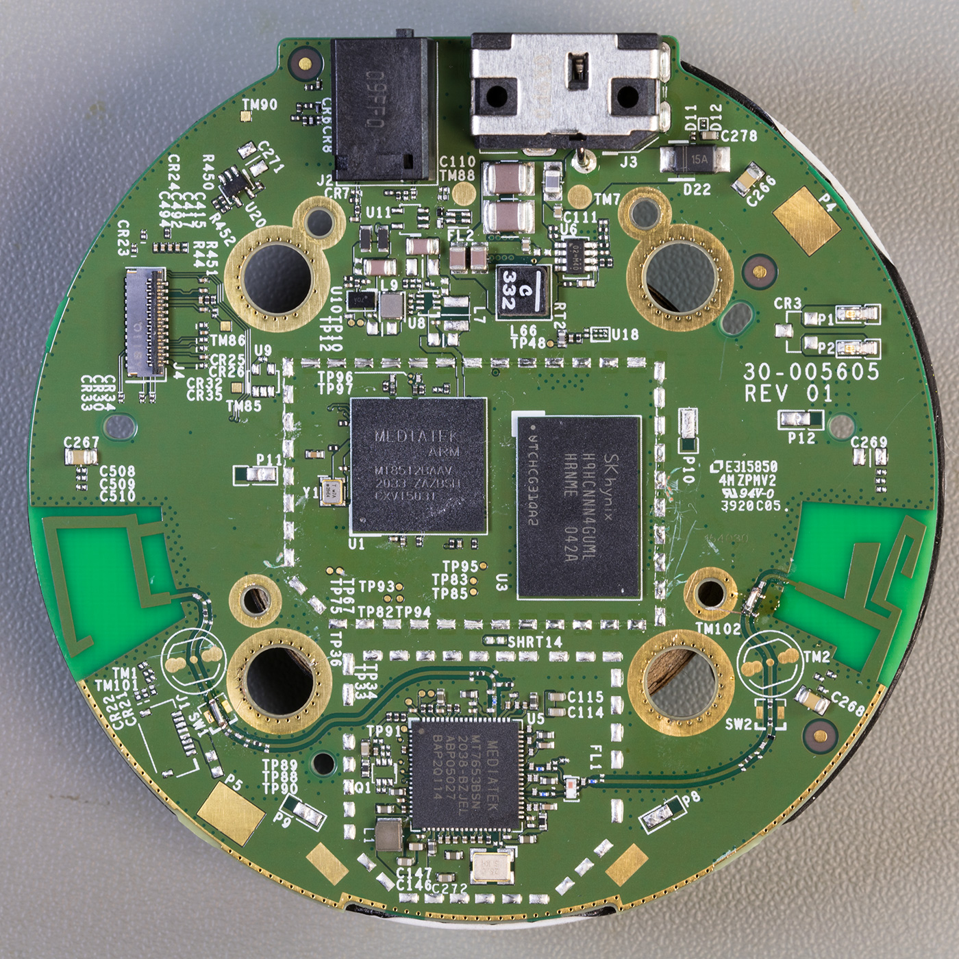
The upper side of the Processor PCB
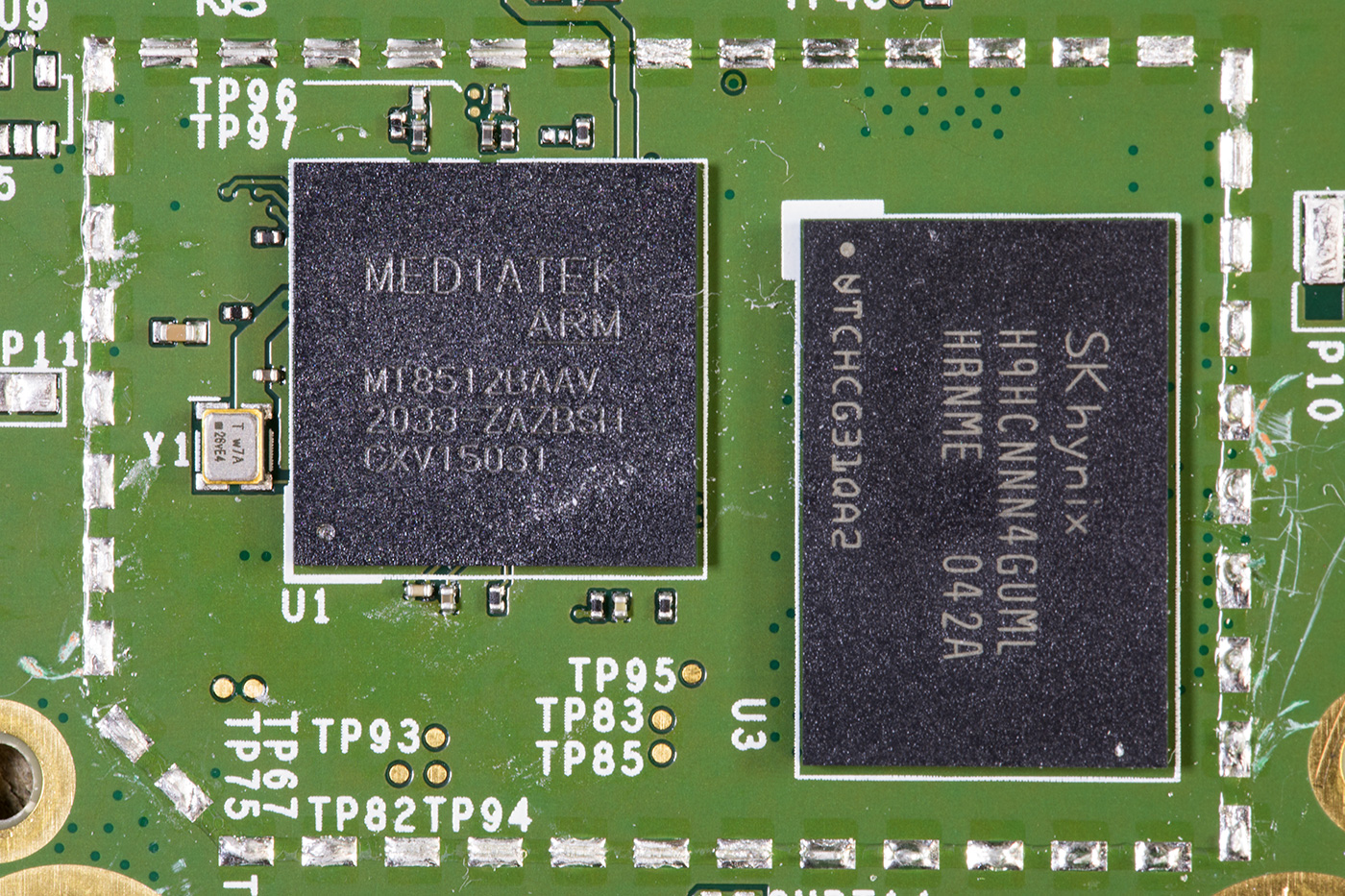
This new version of the Echo Dot uses a different processor than the previous Echo Dot models. A MediaTek 2GHz dual-core ARM CPU with Amazon AZ1 Neural Edge processor, part number MT8512BAAV and an SK Hynix LPDDR4 SDRAM 4G-Bit RAM IC (H9HCNNN4GUML) which are located under a metal shield.
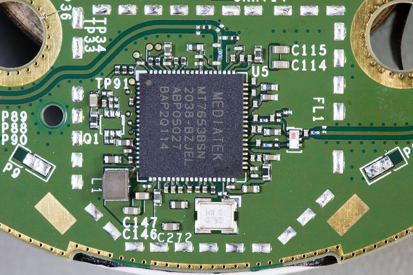
Below the CPU and Ram is a MediaTek Wi-Fi / Bluetooth Controller, part number MT7653BSN which has outputs to two PCB antennas, one on each side of the board.
On the older models of the Echo Dot, the metal shields had removable covers but on the new revision 4, these are soldered to the PCB and require a lot of heat to remove them.
Whilst removing the processor and ram shield with the hot air gun, two of the small components on the RF feeds to the antenna blew away from the board due to the hot air and they had to be replaced with small solder bridges to restore the antenna functionality.
Above the metal shield are the power and speaker sockets.
The processor PCB also contains several power supply ICs to provide the different voltages needed for the unit.
A single flat flex connector links the processor PCB with the top switching and microphone PCB.
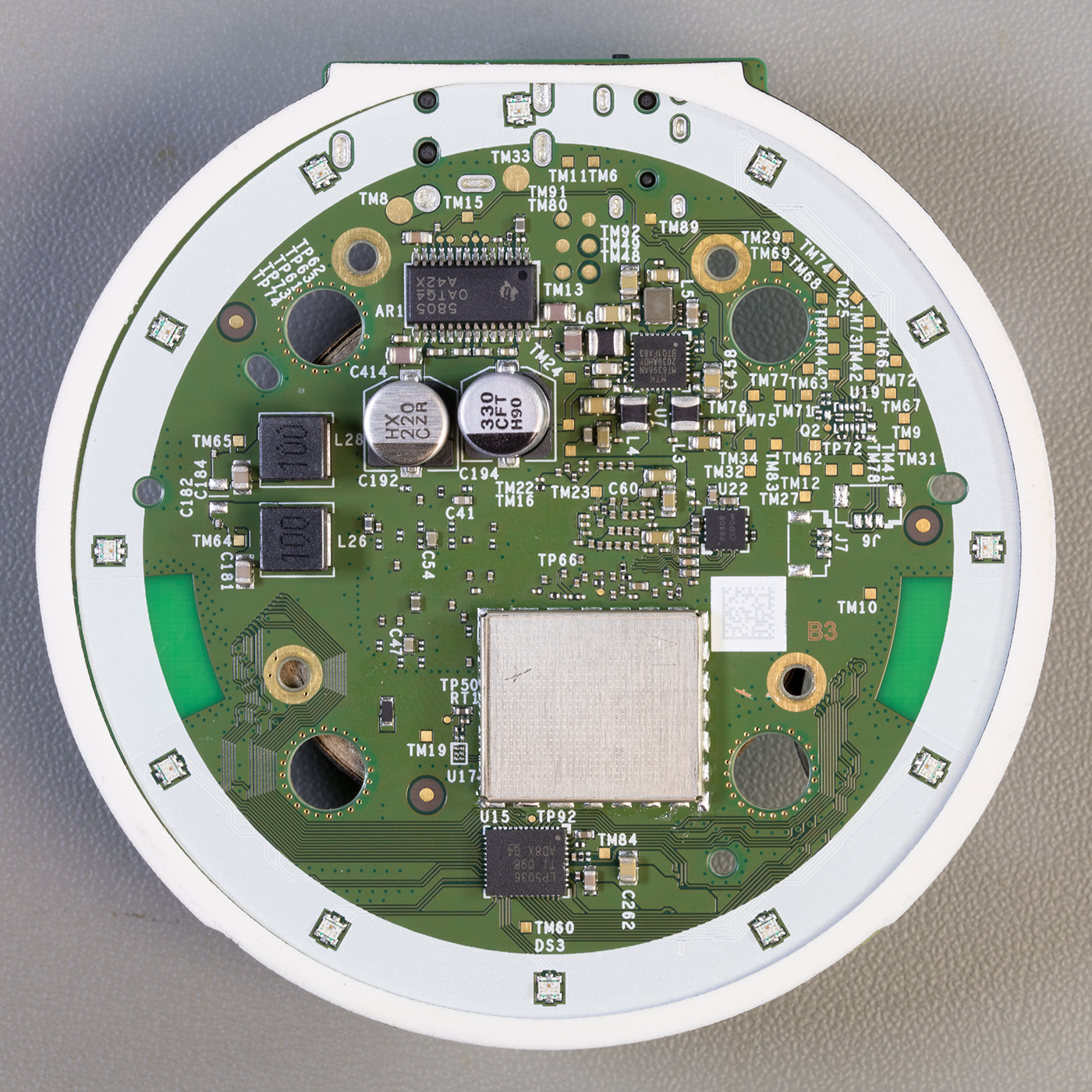
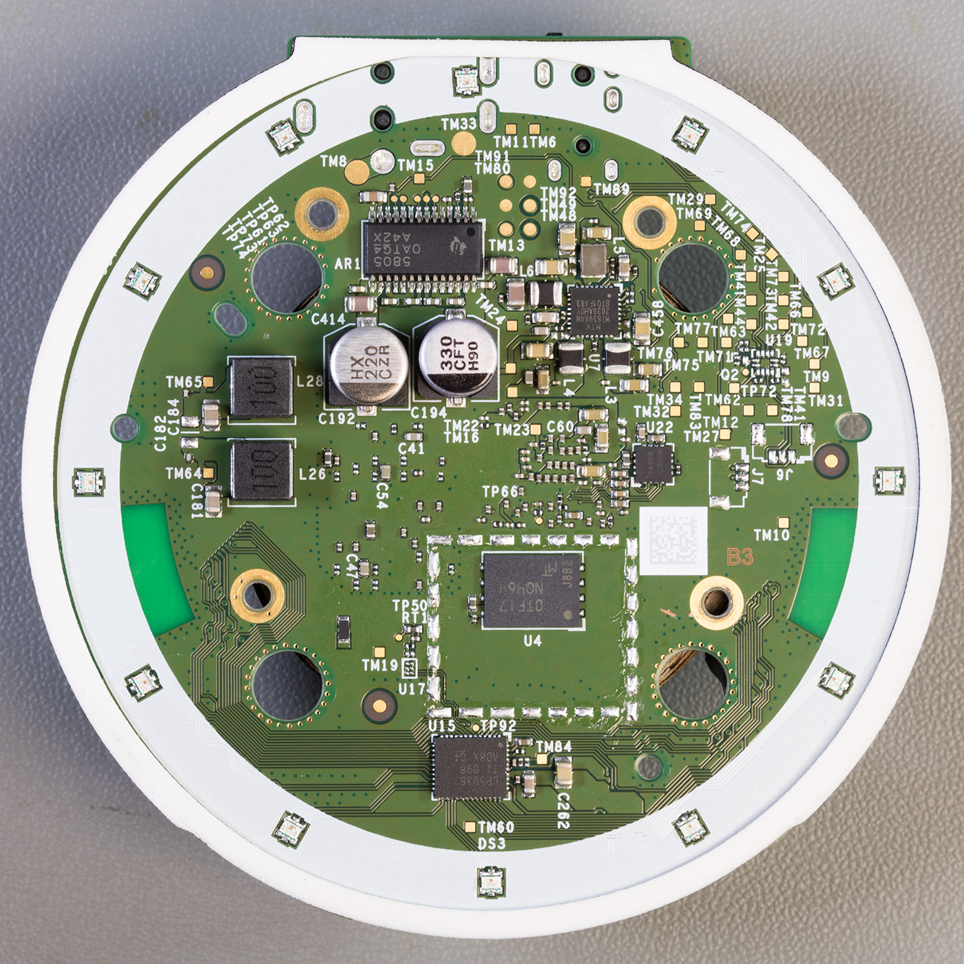
The lower side of the Processor PCB
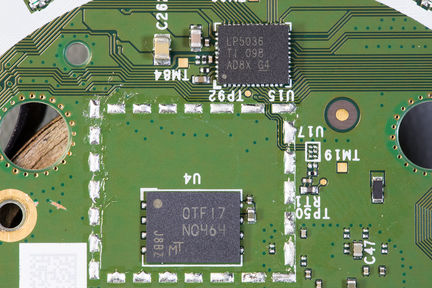
On the lower side of the main PCB are 12 RGB LEDs around the edge which are driven by an LP5036 Texas Instruments 36-channel I2C constant current RGB LED driver.
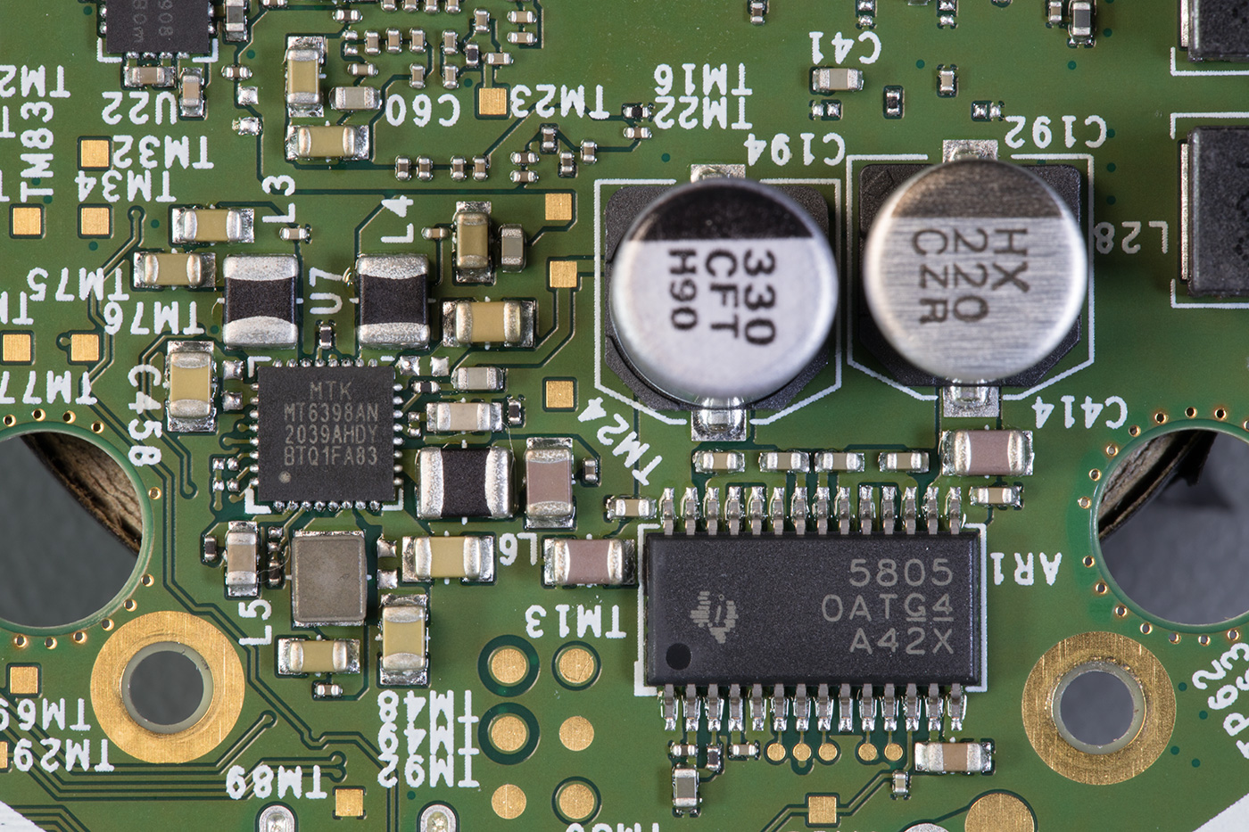
The internal speaker is driven by a TAS5805M Texas Instruments 23-W stereo, 45-W mono, digital input Class-D audio amplifier
The headphone output is driven using a PAM8908 Diodes Incorporated 25mW stereo headphone driver.
Under the metal shield is an MT29F4G01ABAFDWB-IT - Micron 4Gb SPI NAND Flash Memory - Marking NQ464 which contains the operating system.
There is a chip marked MT6398AN which is an unknown MediaTek part but based on the surrounding components it could be a switching PSU.
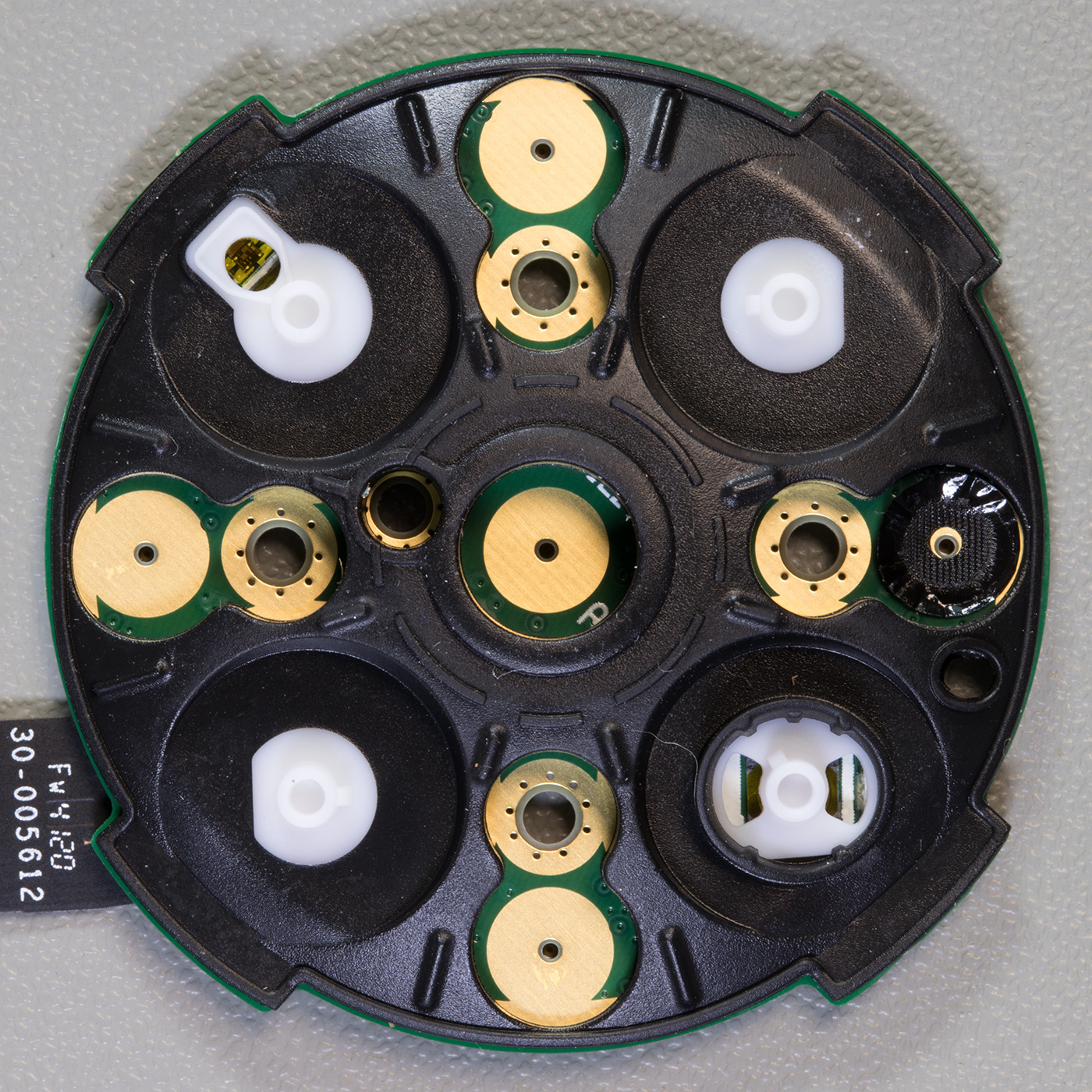
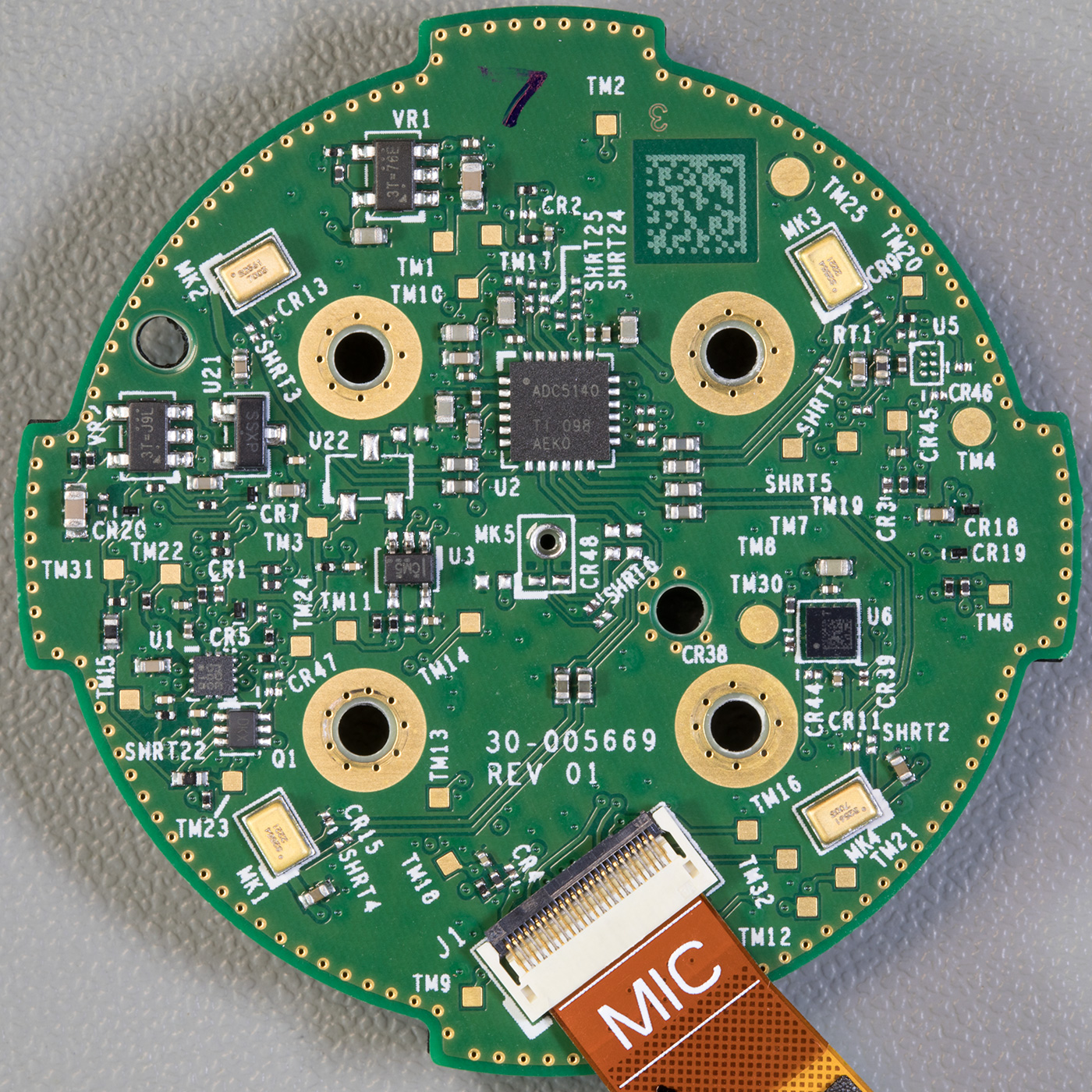
Upper Switch PCB
The small round PCB which is screwed into the top of the case contains four buttons, two LEDs and a light sensor on the upper side with a soft rubber gasket.
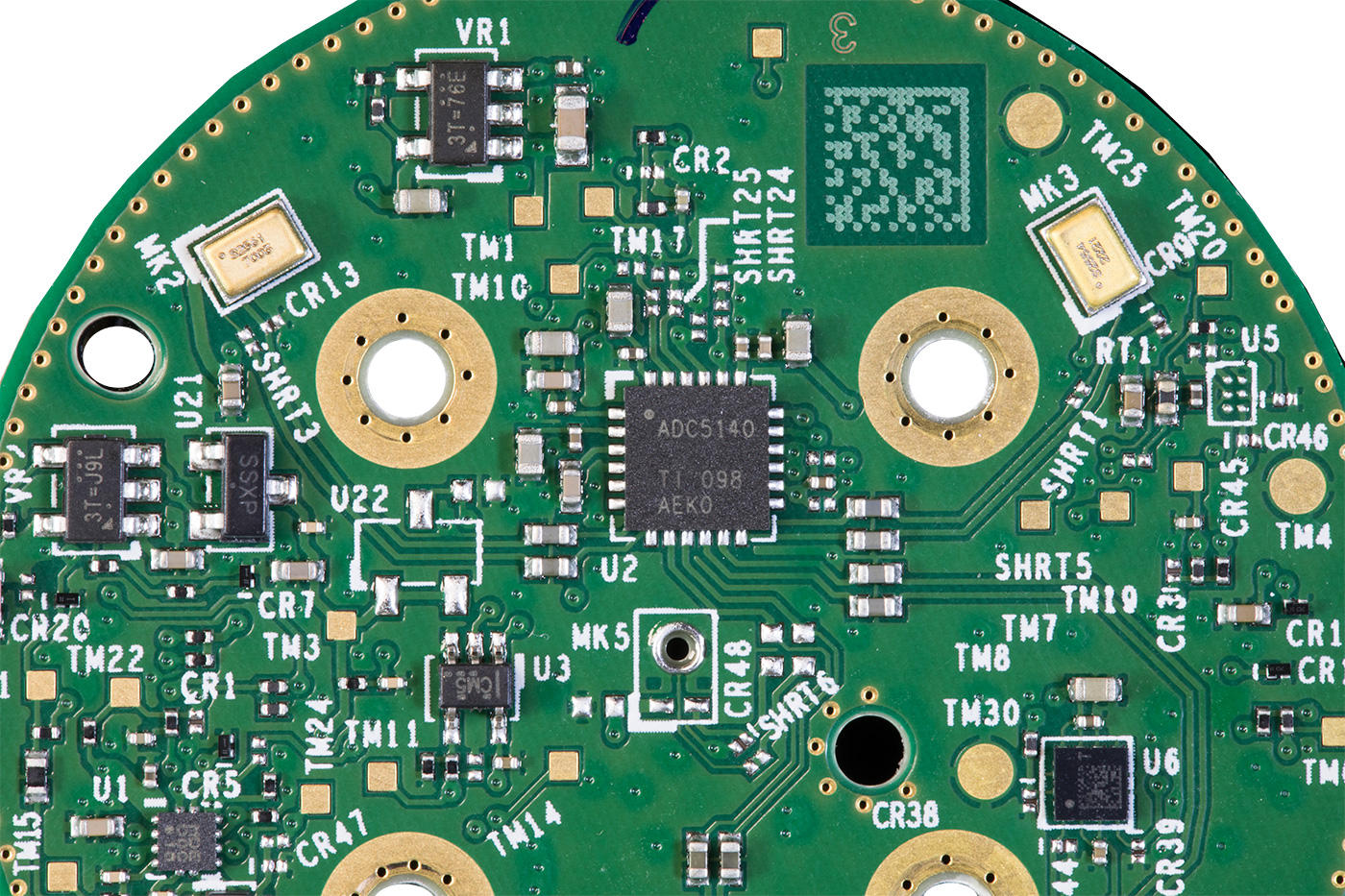
On the reverse of the circuit board are four microphones and a TLV320ADC5140 Texas Instruments Quad-channel 768-kHz Burr-Brown™ audio analogue to digital converter. There are several other smaller ICs on the board, but we could not find any information on what they are.
The Echo dot uses four microphones to locate the direction the voice is coming from and filter out background noise.
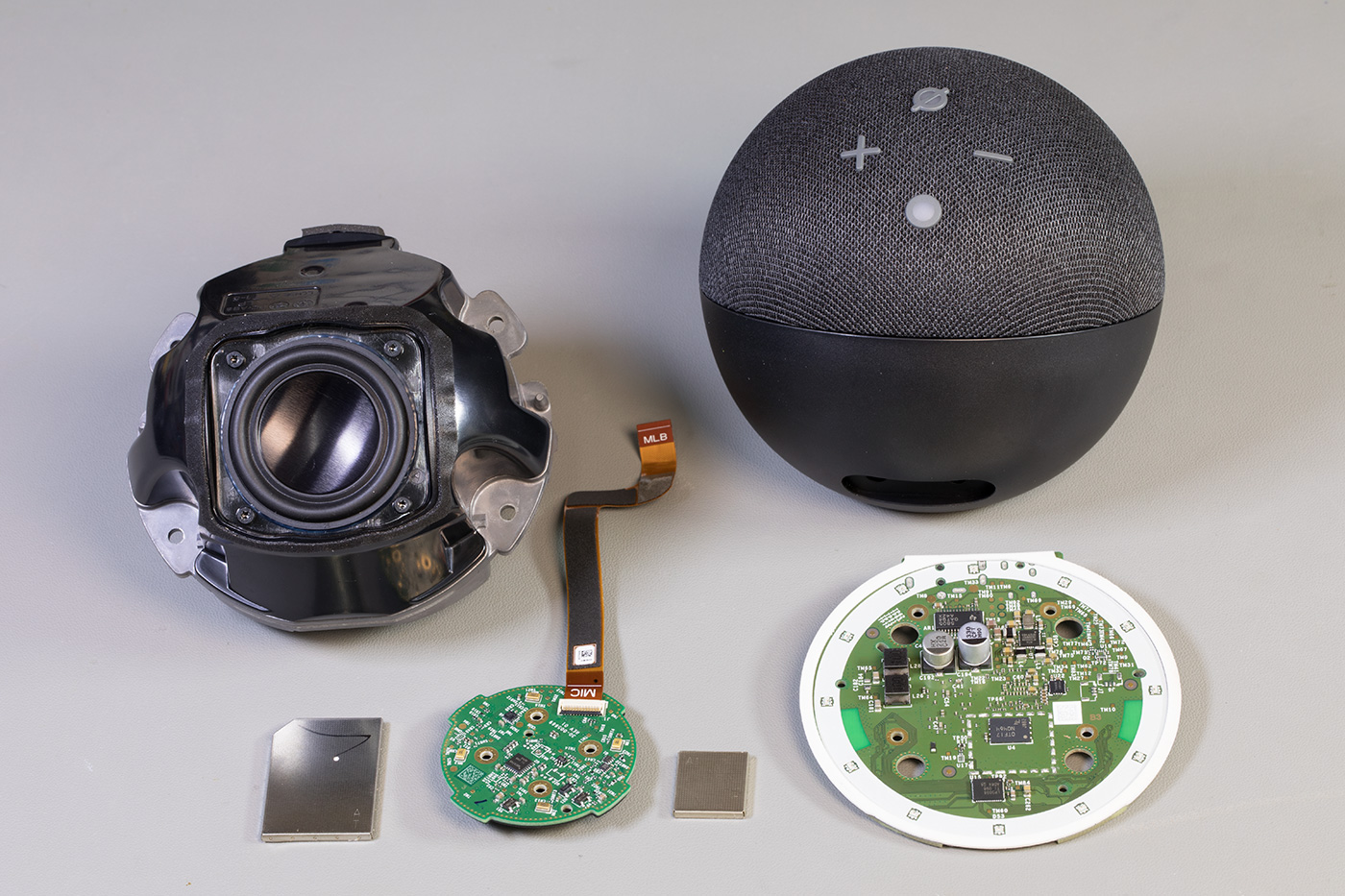
All internal parts
All the internal parts making up the echo dot.
The video below shows the teardown stages.

Rick
Is there a digital potentiometer at the audio amp input? Trying to understand why the dot only had 10 discrete volume levels.
James
The volume is most likely completely controlled by the main processor chip. It is just a digital input in to the amplifier chip.
I would like to know what the sound quality is like on the analogue headphone output that you can use to plug into an external amplifier and speakers. Is it any better than previous generations ??
Vivek
To James Question - I am also interested in knowing if I use Headphones output to drive an external amplifier will be it better than 3rd Gen. I went through the specs for the chips you mentioned above, I could not understand what shall I looking for?
Thomas
Thanks for this detailed report.
Andrew
Has anyone had any luck unlocking the bootloader?
H Wolfe
Is the speaker the same as the 3 gen dot or improved?
Stephan
Thanks for looking inside!
I'd like to know if I could power the dot 4 with 15V DC and if the voltage regulator part is ready for this. I guess there are DC DC step downs in there... U6? Has anybody a datasheet or informations about this?
Thanks and best regards!
Abhishek
How Echo Dot (4th Generation) is different from Amazon Echo (4th Generation) and out of these two devices which one is MIMO.
Abhishek
I want to know whether MT7653BSN WIFI and Bluetooth chip is having single-antenna WiFi or dual-antenna WiFi. Also please tell how to check if a Mediatek WIFI/Bluetooth chip is having dual-antenna WiFi or single-antenna WiFi.
Eduardo
gostaria de saber onde encontro o esquema elétrico com os valores de cada componente pois estou tendo dificuldades em reparar uma echo dot 4 que desliga sozinha
I would like to know where I can find the electrical schematic with the values ??of each component because I am having difficulties in repairing an echo dot 4 that turns itself off
Lucas
This Echo 4th is looking good in this price range. The price segment is looking satisfactory! I would love to try this Mediatek-powered device.
Boris
Echo Dot 5 teardown soon? I heard it's using the AZ2 chipset.
Edinelson Farias de Souza
Alguém sabe dizer qual é o modelo desse auto falante?
Does anyone know what model this speaker is?
Bob
Unfortunately, this device is now absolute garbage! Or Amazon has downgraded the firmware so that people buy newer devices!
Earlier functions no longer work at all! Just as a small example. When I bought this device, I was able to save the radio stations that I last listened to. Now you can't even find this option in the app settings! And the Echo always starts with the same station and can no longer be changed.
It's the same with many other functions (e.g. alarm clock...), they no longer work or are no longer available!
Pure Amazon rip-off!
Chi
I can't charge mine. I've bought it but never used it for years, then suddenly decided last week. I am sure the charger is in good condition just the equipment won't start. What am I missing?
Mahesh
Sir my alexa 4 th gen device has bluetooth and wifi issue the complaint is the main board so you purchase a new board are repair the device
beadam
I have a modal politely different. it's an echo dot 4 but when i opened it up i found debugging pings where the 6 should be. i want to connect to my computer via UART to play around with it. but i coudn't figure out the pins layout.
FELIPE
Tengo este modelo.
De repente dejó de funcionar y se calient en exceso.
Lo desmonto y es la placa superior donde van los pulsadores.
Parece que un procesador se calienta a tope y hasta la cinta de unión de placas se calienta un montón.
Hay repuestos de esto?
Gracias