We have previously torn down several Amazon Echo devices including the 3rd gen Dot, the Flex and the Echo Input. In this teardown, we will look at the Echo Dot 3rd gen with a clock.
Most of this Echo Dot is the same as the normal 3rd gen model with the main differences on the processor board and the clock board so if you have read our previous teardown you can jump to the processor board to see the differences.
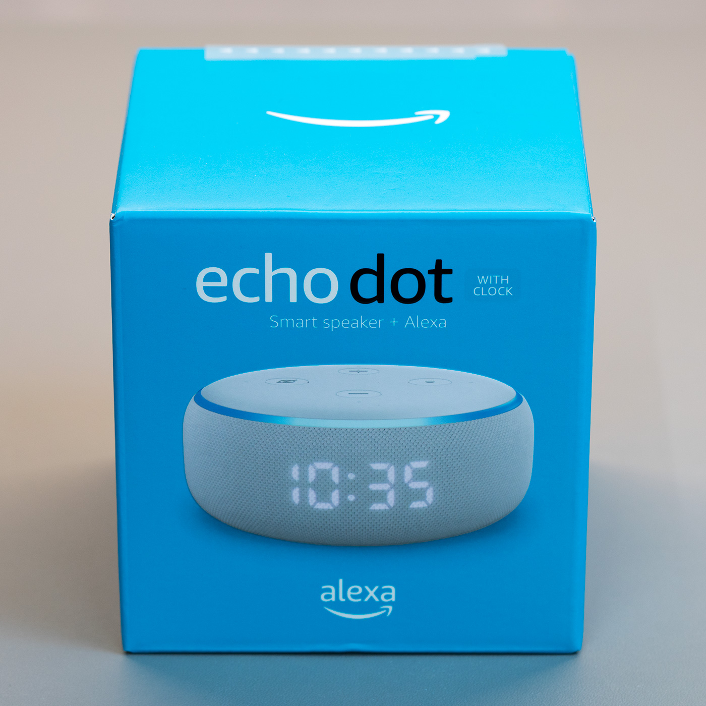
In the Box
- The Echo Dot
- 240V UK power supply
- Things to try leaflet
- Setup instructions
- Echo Dot terms of use
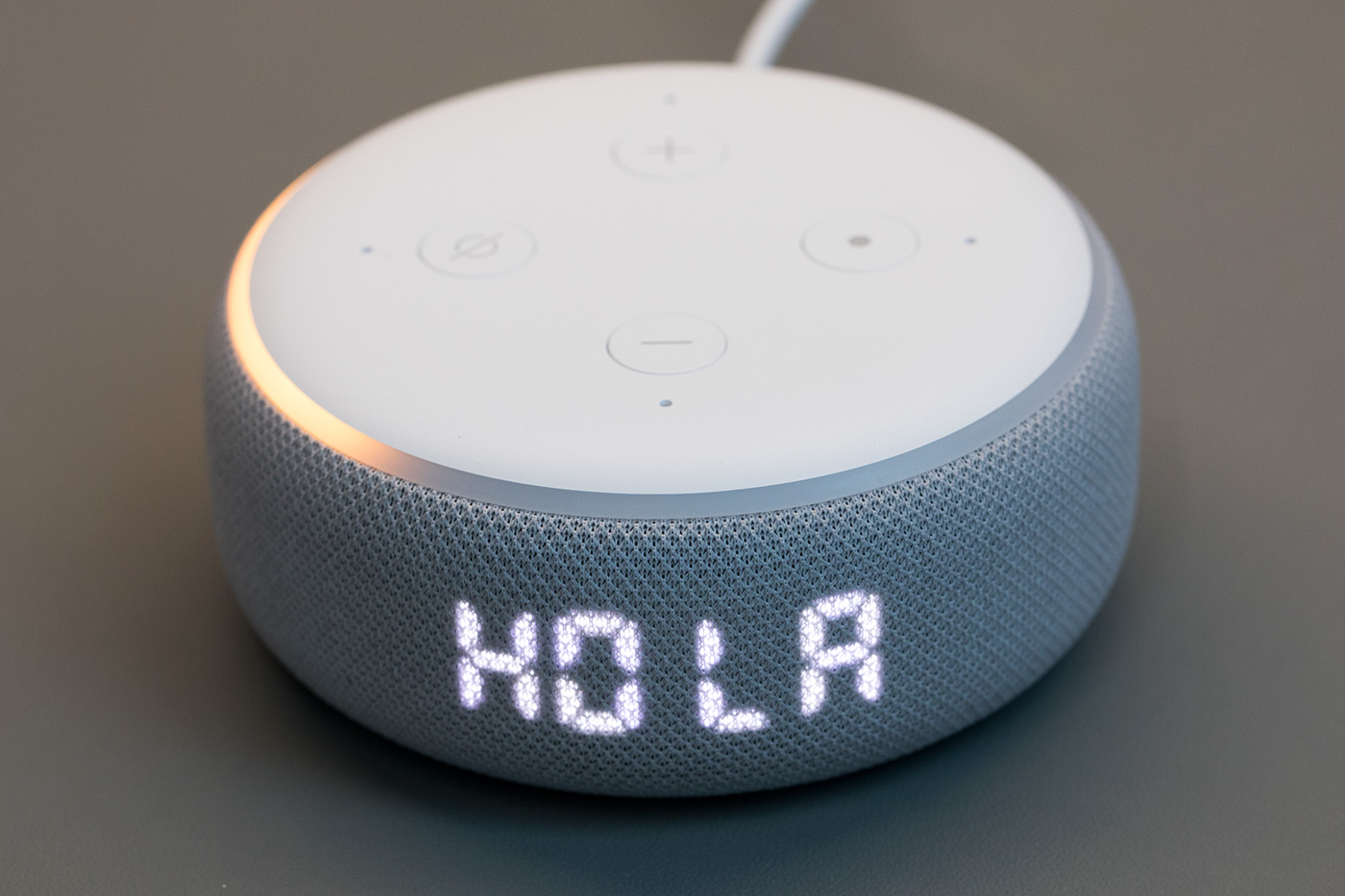
Top of the Echo
The top of the echo dot has four buttons, four microphones and an LED ring. The + and – buttons control the volume; the circle button activates Alexa and the circle with a line through it enables or disables the microphones.
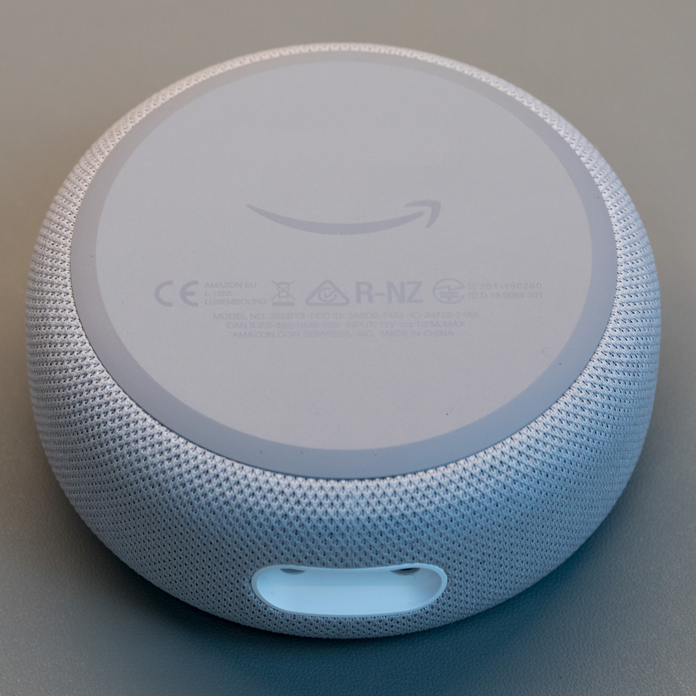
Case Base
The base has the serial number, product logos and certification marks.
On the side are a power input socket and headphone/audio out 3.5mm stereo socket.
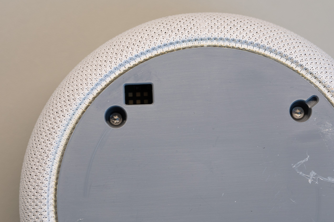
Case Base with sticky foot removed
The cover is held in place using adhesive tape and four plastic locator pins.
To open the case first you need to remove the non-slip rubber cover on the base of the echo dot, using a thin knife or some other flat-bladed tool.
Under the cover, you will find four Torx bolts and a recessed six-pin header which appears to be a debug or programming port.
Removing the four Torx bolts allows you to remove the plastic base.
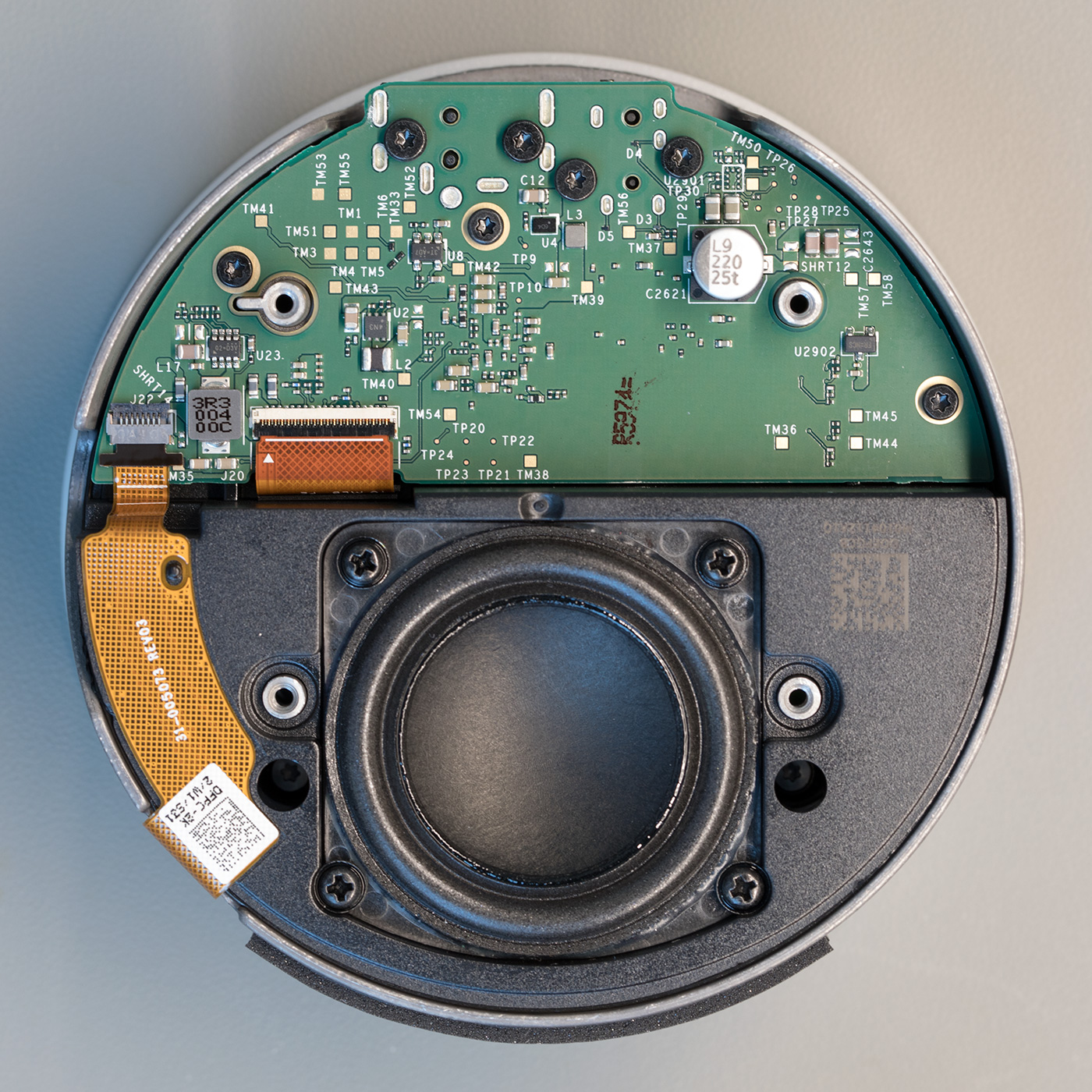
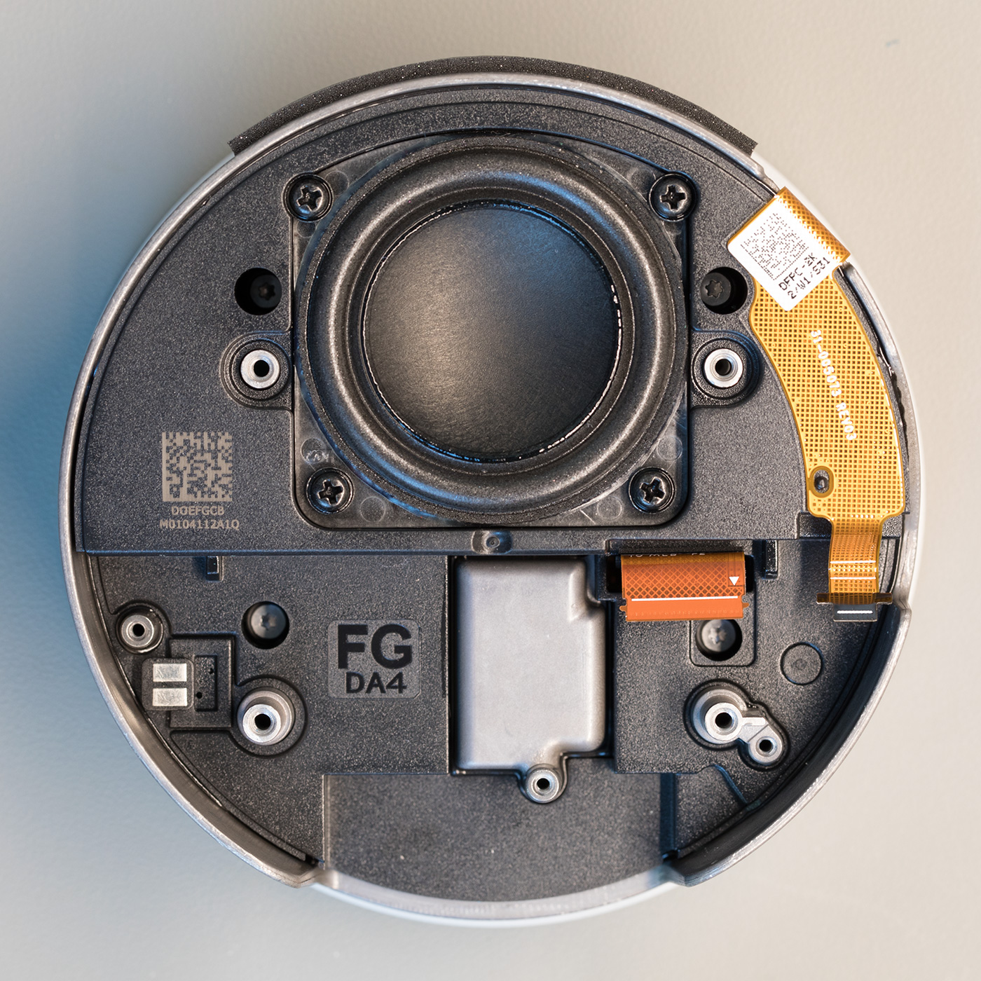
Metal Chassis with Processor PCB and speaker
Inside you will find a circuit board and an internal speaker.
The underside of the PCB contains discrete components and several test points.
The base PCB is removed using three Torx bolts and the removal of a small flat-flex cable. The four bolts that hold the power and headphone connectors down do not need to be removed.
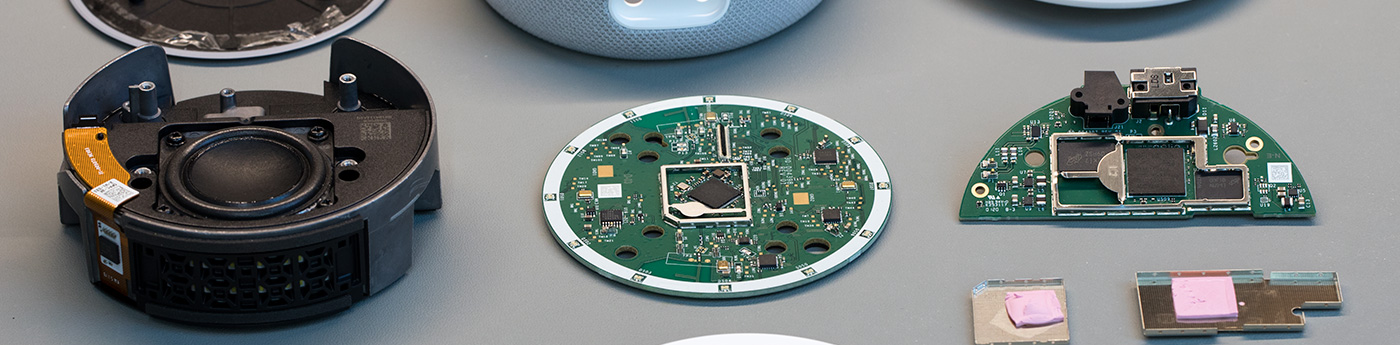
Processor PCB
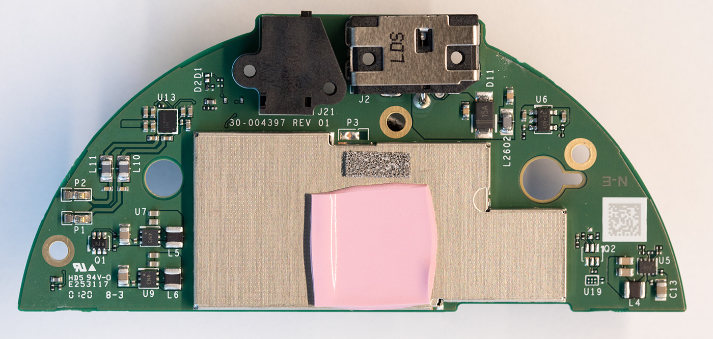
The processor PCB contains most of the changes compared to the original Echo Dot 3rd gen.
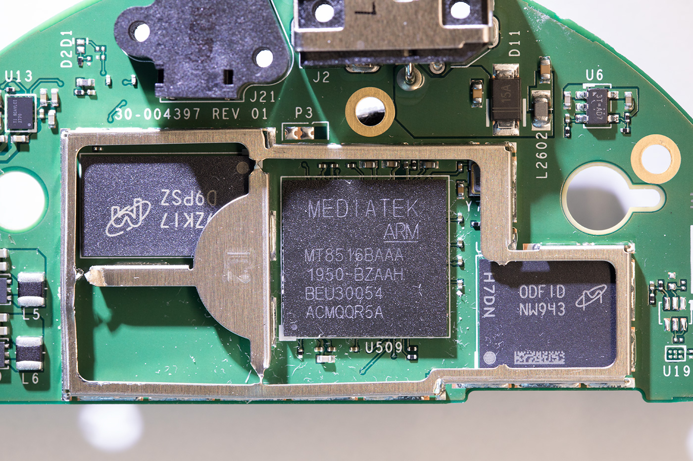
This version of the Echo Dot uses the same MediaTek MT8516BAAA processor but the combined DDR ram and NAND memory chip on the original Echo has been replaced with two chips. An MT41K128M16JT-107 DDR3 2Gb RAM chip provides the memory while an MT29F4G08ABAFAH4-IT 4Gb Serial NAND Flash chip provides the storage.
The processor, RAM and storage are enclosed inside a metal shield that can be removed using a small screwdriver.
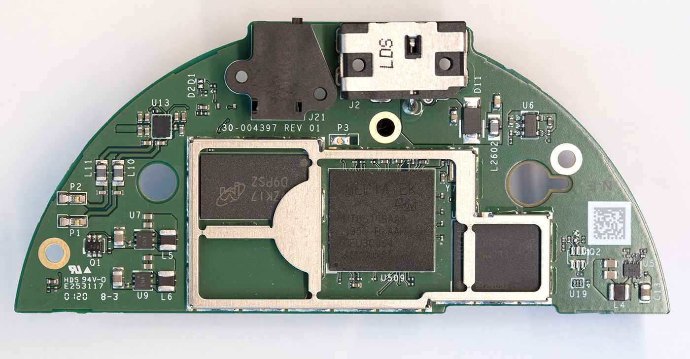
Next to the metal shield are the power and speaker sockets.
The processor PCB also contains several power supply ICs to provide the different voltages needed for the device and a TAS2770 20W amplifier from Texas Instruments which provides the audio for the speaker.
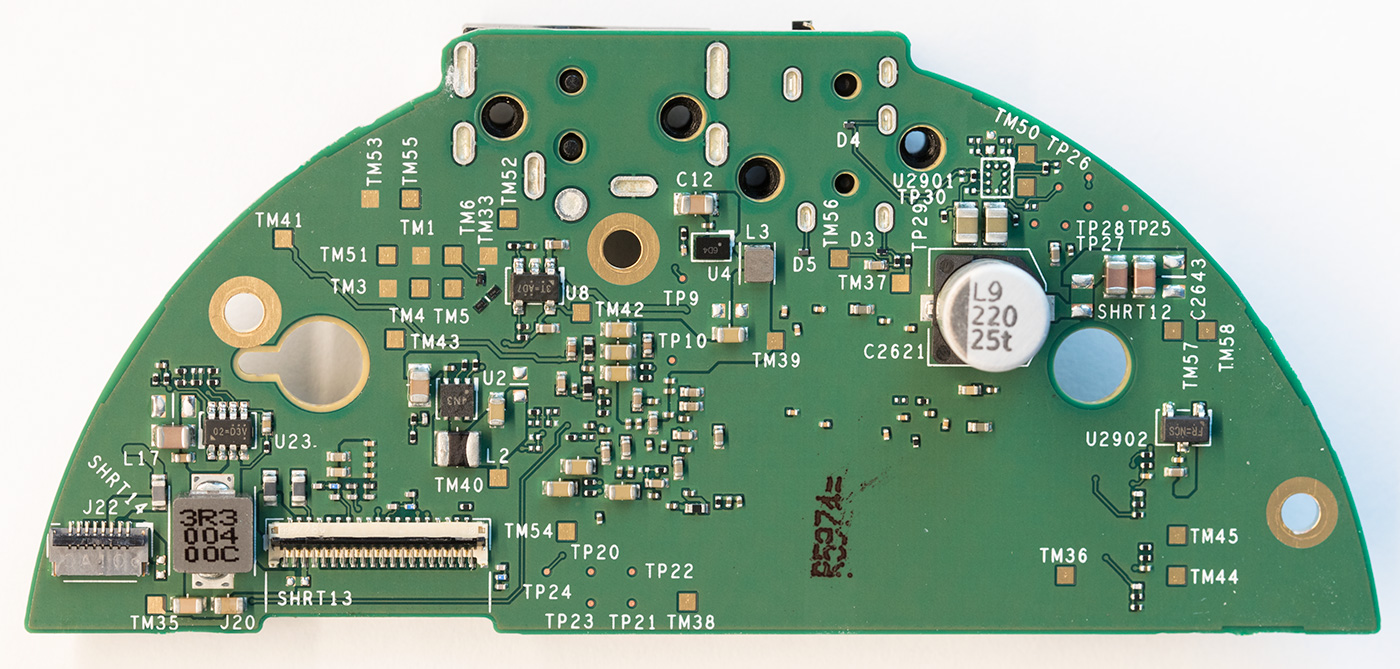
On the back of the PCB, you will find more power supply circuits and two flat flex connectors. One links the processor PCB with the top PCB and the other connects to the clock PCB on the side of the metal chassis.
Top PCB with White Plastic surround
The top of the PCB contains four buttons, two LEDs and a light sensor. The product number of this PCB is different from the original Echo Dot 3rd gen, but it appears to be identical to the old board.

On the top of the board, you can find four buttons, some LEDs and a light sensor. The LEDs are placed on either side of the button which toggles the microphones on and off. The light sensor controls the brightness of the LED ring array.
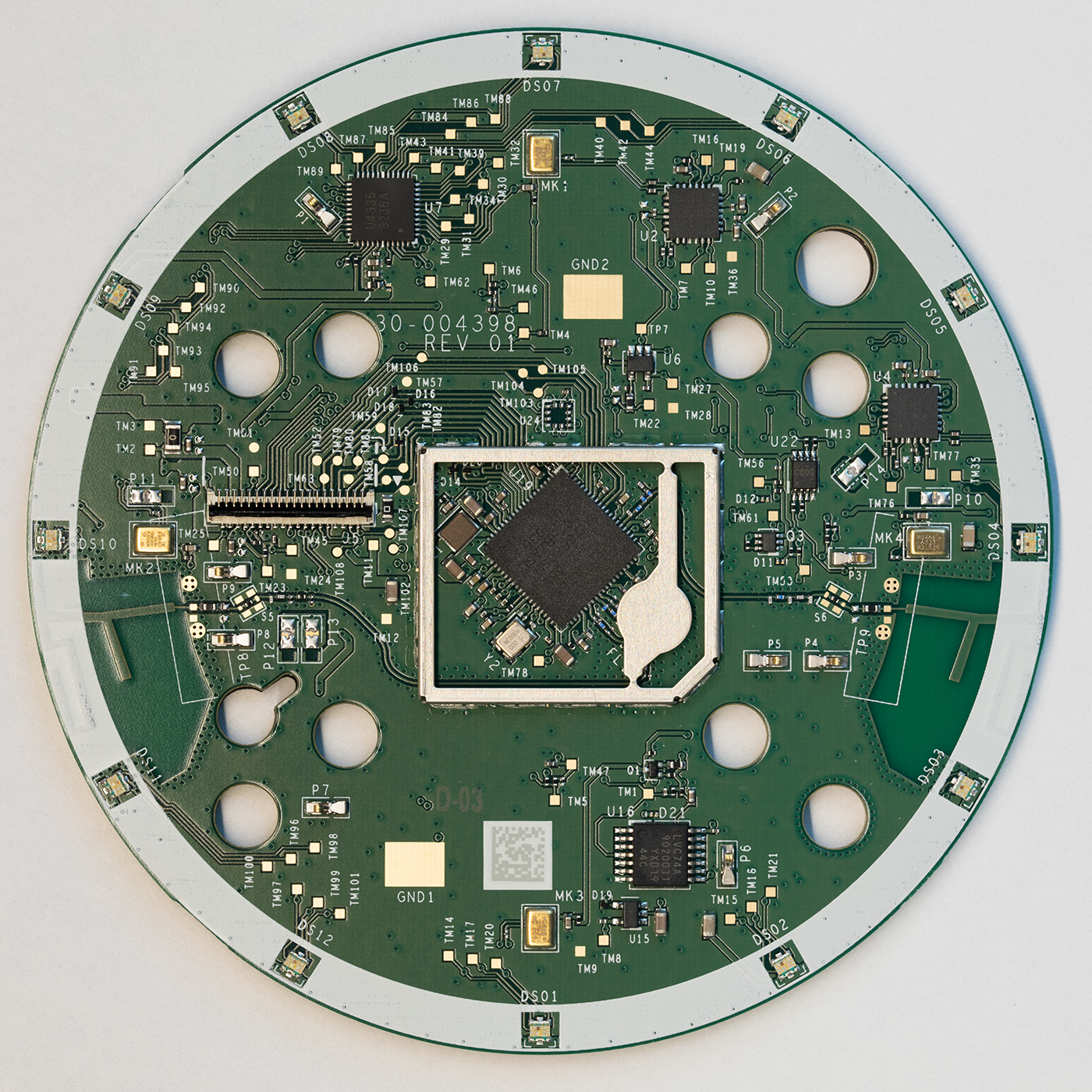
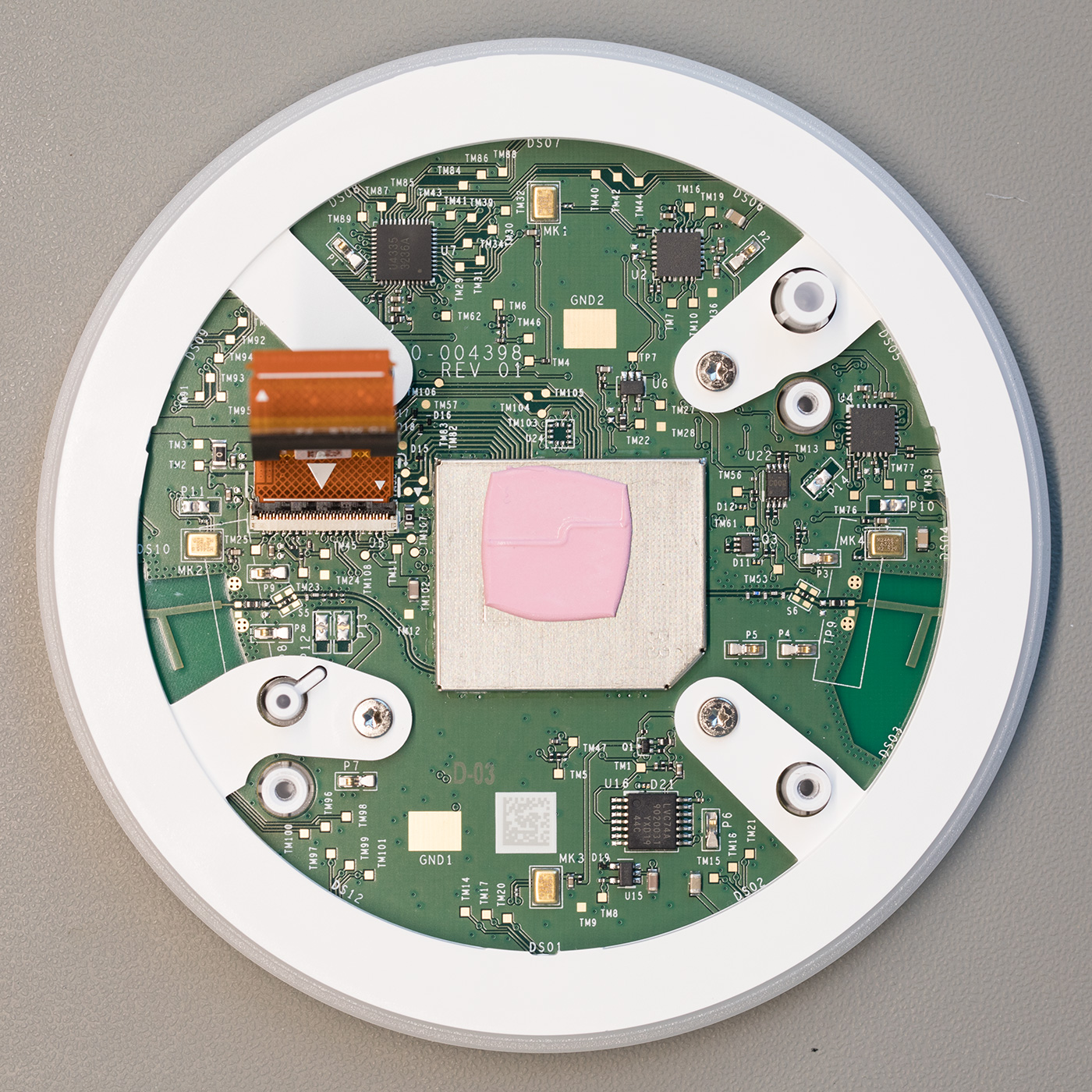
The underside of the top PCB contains most of the components found inside the Echo Dot. An array of 12 RGB LEDs is located around the edge of the board. The LEDs are driven using an ISSI IS31FL3236 36-channel LED driver.
Four microphones are placed next to the buttons and these feed into two TLV320ADC3101 chips from Texas Instruments. The TLV320ADC3101 is a Stereo ADC with an embedded mini digital signal processor. The Echo dot uses four microphones to locate the direction the voice is coming from and filter out background noise.
In the centre of the PCB is a metal shield. Under the shield, you will find a MediaTek MT7658CSN dual-band Wi-Fi and Bluetooth controller with an ARM Cortex-R4 CPU. The MT7658CSN manages communication to wi-fi and Bluetooth devices and connects to two PCB antennas located on the outer edges of the board.
There is also a Fairchild 74LCX74 dual D-Type flip-flop which appears to switch the microphones on and off.
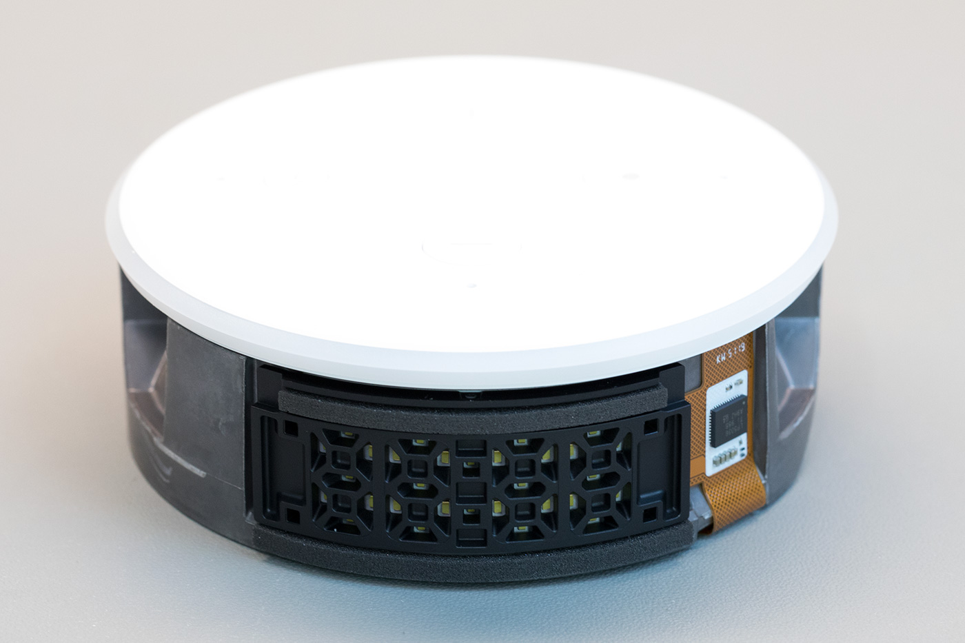
Metal Chassis with Speaker
The Metal chassis contains the clock module, the speaker and plastic moulding for the speaker. The plastic surround for the clock and speaker is glued to the metal chassis, so we did not try to remove this.
There are four recessed Torx bolts which hold the top panel to the metal chassis.
Removing these allows you to remove the top PCB and button panel.
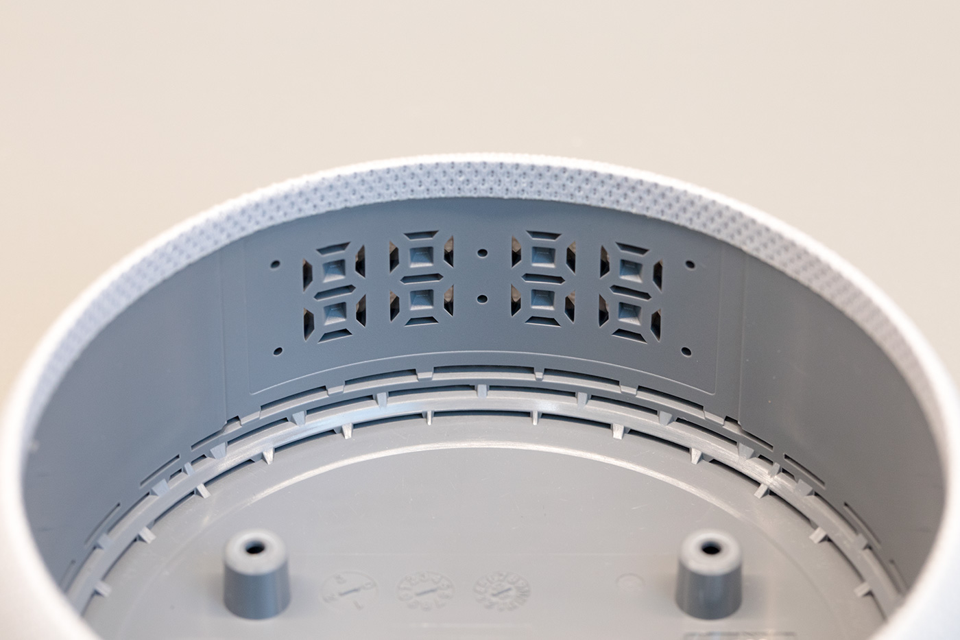
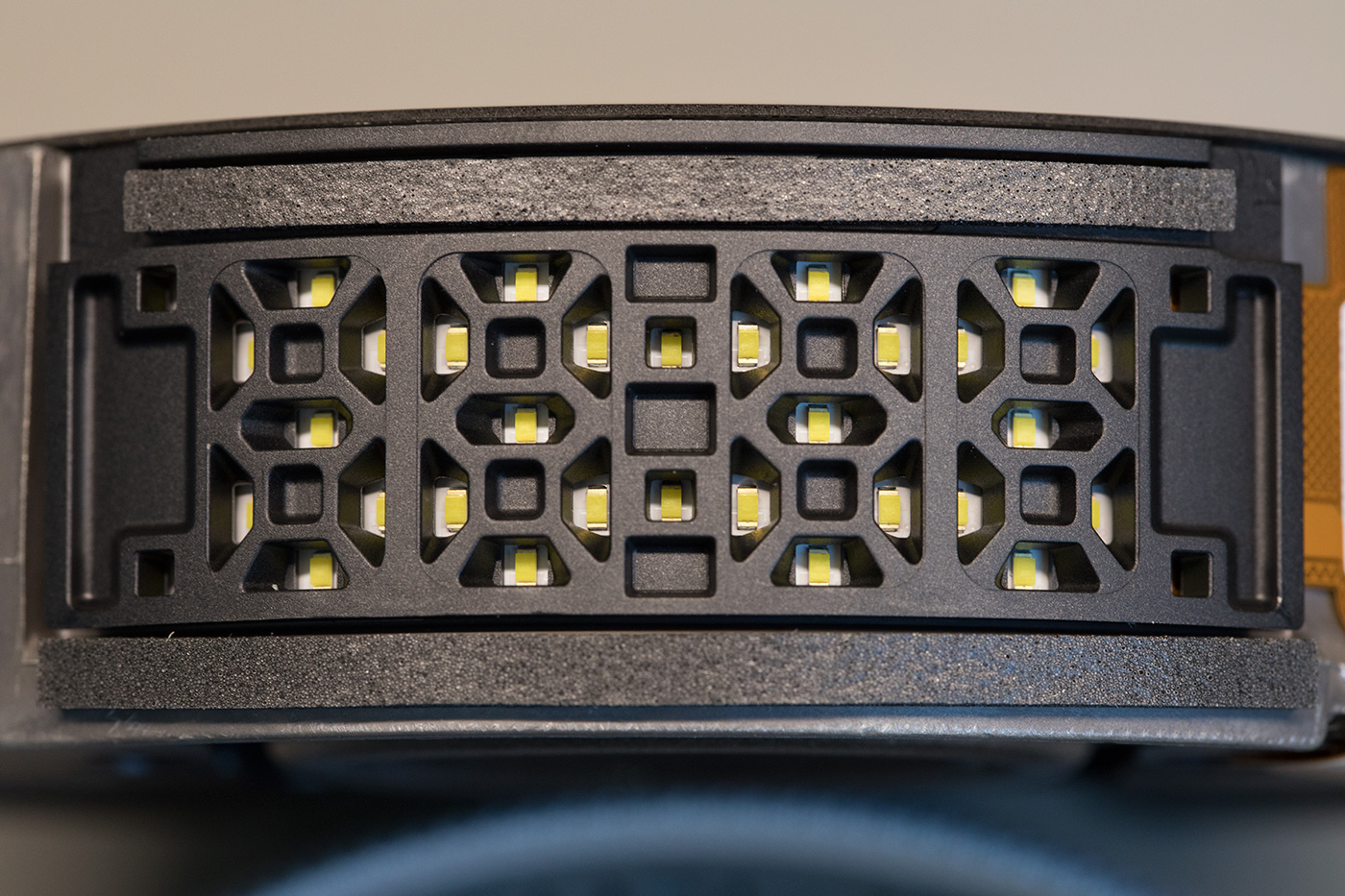
On the side of the chassis is the clock module. The clock display consists of a flat flex PCB with 30 LEDs arranged as four 7-segment numbers and two dividing LEDs in the middle. The LEDs are sat behind a plastic moulding which creates the shape of the 7 segments. The side of the case also has the same cut-outs so from the outside it looks like four normal 7-segment LED displays.
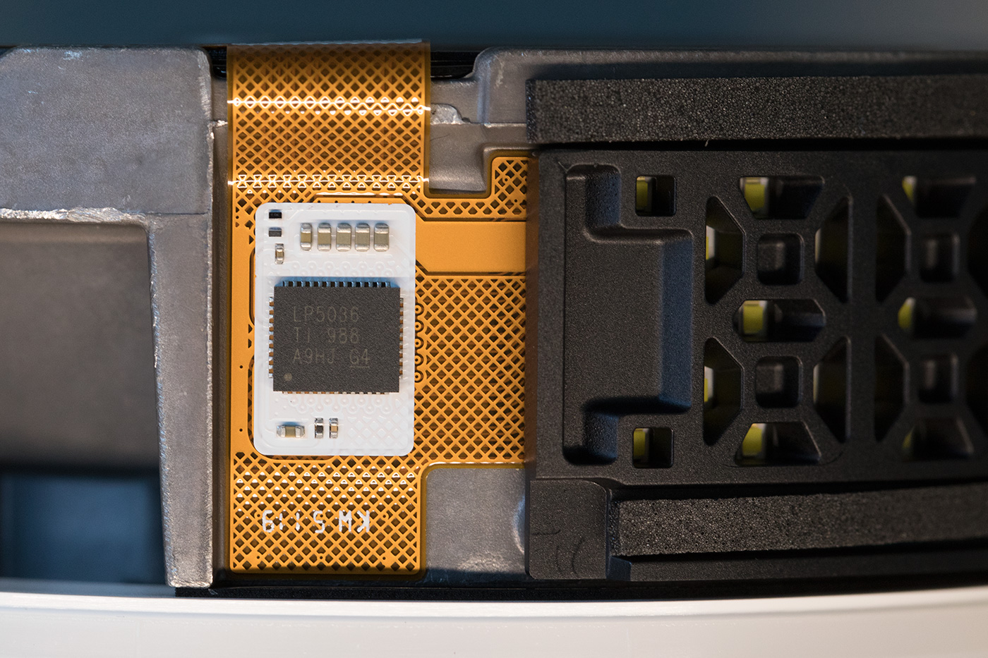
The LEDs are driven using an LP5036 36-channel I2C constant current RGB LED driver from Texas Instruments. A small flat flex cable joins the clock PCB to the processor board and provides the power and I2C bus for the display.
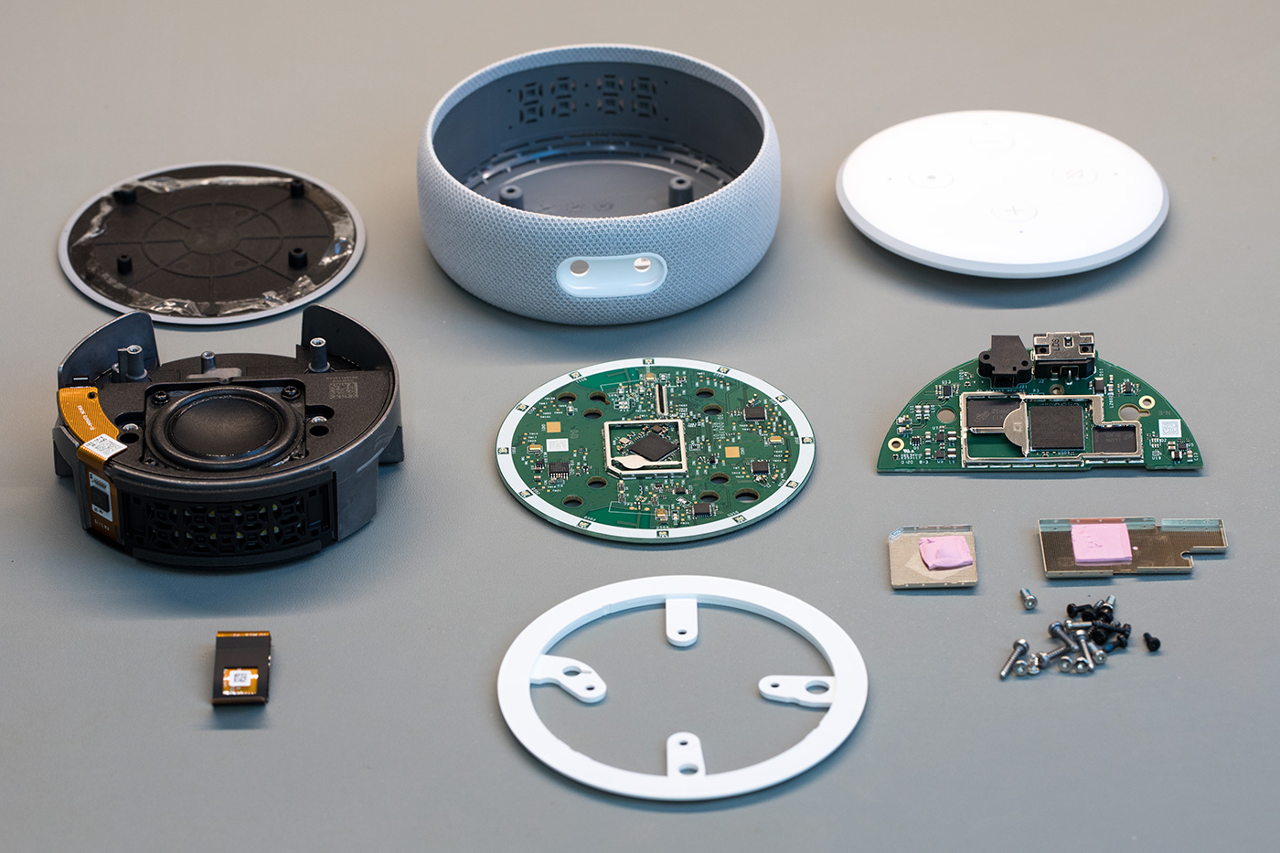
All internal parts
All the internal parts which make up the echo dot.
The video below shows the teardown stages.

Dharmesh
NIce teardown of this Amazon echo dot smart speaker. By any chance do you know the music power in watts of this smart speaker
Brian
Dharmesh, i am sorry but I do not know the watts rating of the speaker
j
DO you know what cable i can use to connect to an external battery?
Brian
You could use the power cable to connect to a 5v battery supply.