For several years we have used the Zwift online training software which connects to a smart trainer to allow us to continue cycling in the winter months when the weather is too wet to cycle outside.
When cycle training using Zwift you can use a mobile phone as a secondary display and use keyboard commands to activate things such as screen capture, power ups, change display mode, change direction etc.
One issue I often find when using Zwift with the mobile phone companion app is needing to keep scrolling on the screens to find the button I need and when you are very sweaty this does not always result in the correct button being pressed.
The ideal solution for this would be to have handlebar mounted physical buttons which are mapped to the Zwift commands required. Zwift sells a handlebar controller called the Zwift Play but this is not fully compatible with my bikes smart trainer for virtual shifting and it does not appear to be possible to remap the buttons.
After looking at different options for wireless Bluetooth keyboards and not finding any commercial products which would do everything we need, we decided to build our own based on an Adafruit ESP32 Feather board which can function as a Bluetooth keyboard and have the inputs assigned to any key commands we need.
The Adafruit ESP32 Feather V2 has 8MB Flash and 2 MB PSRAM. The boards can be powered by USB type C or Lipoly battery and has built-in battery charging when powered over USB-C. The Feather board has a ESP32 Dual core 240MHz Xtensa processor and supports both Wi-Fi and Bluetooth stacks.
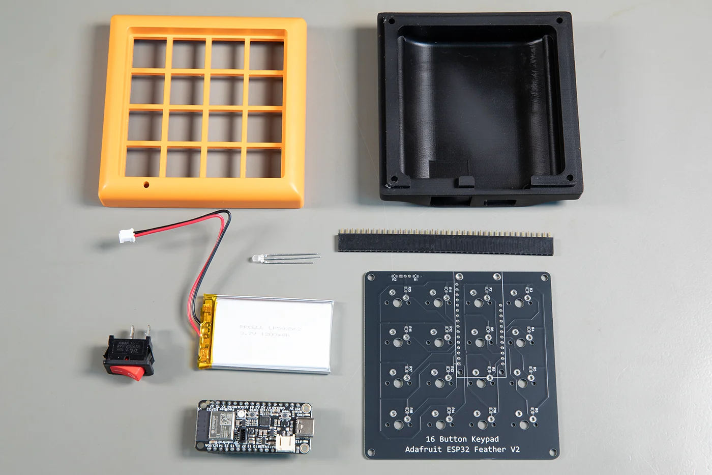
Circuit Design
The circuit uses 16 Cherry MX keyboard switches mapped to individual pins on the ESP32 module. A 1200mAh 3.7V LiPo Battery is used to power the circuit. The battery is switched using a toggle switch on the back of the case. A red-green led is used to show when the keyboard is switched on as well as the charge status of the battery. We designed a custom plastic case which we ordered from jlc3dp.com/ using SLA resin, with JLC Black Resin for the base and LEDO 6060 Resin painted orange for the top cover.
The printed circuit board was designed in DipTrace and ordered from jlcpcb.com. The design files can be downloaded from GitHub.
Parts Required:
| Part | Quantity | Price | Link |
|---|---|---|---|
| Adafruit ESP32 Feather V2 with Headers - 8MB Flash + 2 MB PSRAM - STEMMA QT | 1 | £20.10 | The Pi Hut |
| 1200mAh 3.7V LiPo Battery | 1 | £8 | The Pi Hut |
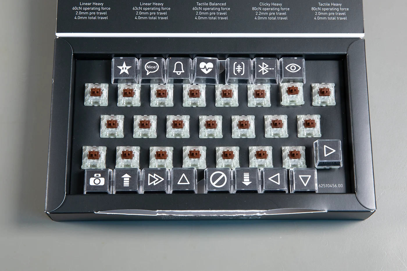
| CHERRY MX Brown Switch Kit, 23 Mechanical Keyboard Switches | 1 | £12.86 | Amazon (Affiliate link) |
| Transparent Keycaps Double-layer Keycaps | 20 | £1.14 | Aliexpress |
| PCB | 1 | $3.20 | jlcpcb |
| 3D Printed Case | 1 | $19.78 | jlc3dp |
| 2.54 Single row socket header, cut to fit 16 and 12 holes | Min order of 5 | £4.37 | RS Components |
| 10K 0805 Resistor | 16 | £3.96 | RS Components |
| 180R 0805 Resistor | 2 | £1.55 | RS Components |
| Green & Red LED 3mm Through Hole | 1 | £0.59 | RS Components |
| Power Switch | 1 | £1.87 | RS Components |
| M3 Bolts, 12mm Length | 4 | eBay lowest price | |
| Double sided sticky pads for battery mounting | 1 | eBay lowest price |
Assembly
The PCB requires 10K pull-down resistors for each of the buttons and 180R resistors for the LED. These are soldered to the bottom of the PCB.
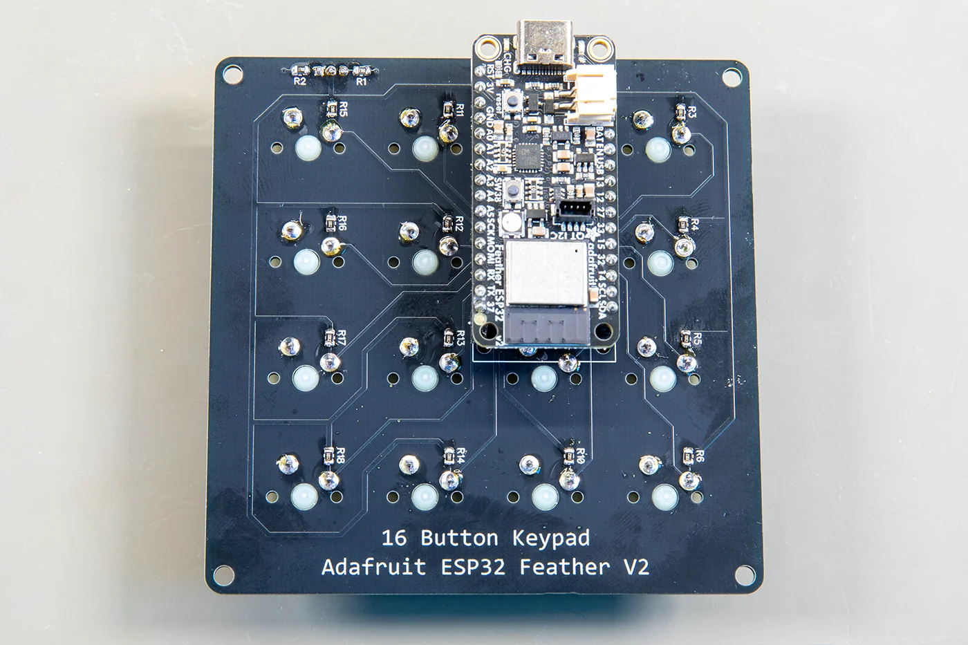
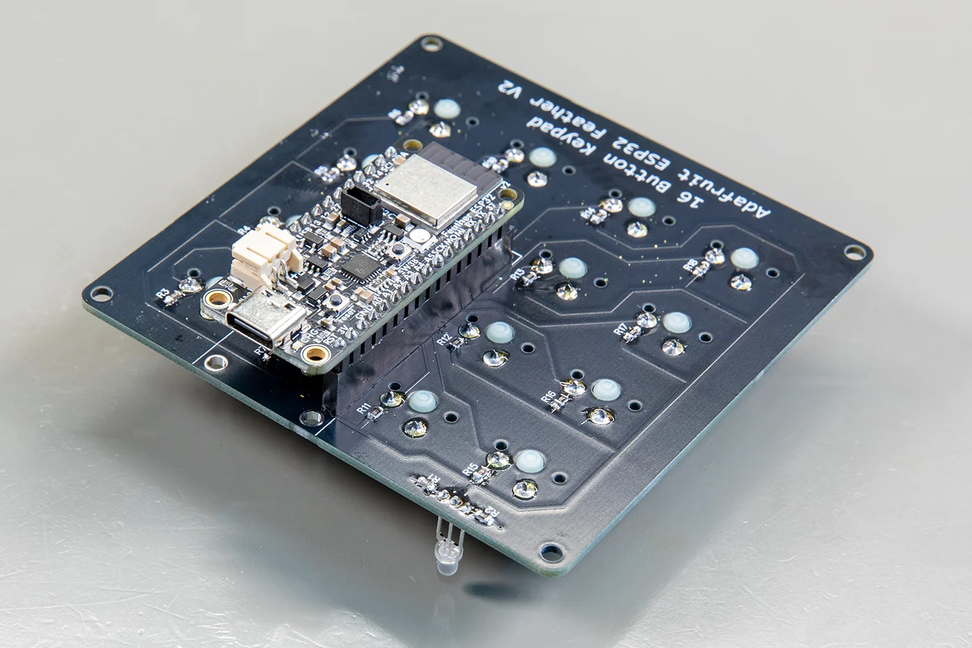
The single row sockets are then soldered to the bottom of the PCB. To aid alignment it is easier to install if you fit the feather board into the sockets.
The Cherry MX switches are then soldered to the top of the PCB taking care that they are all aligned correctly.
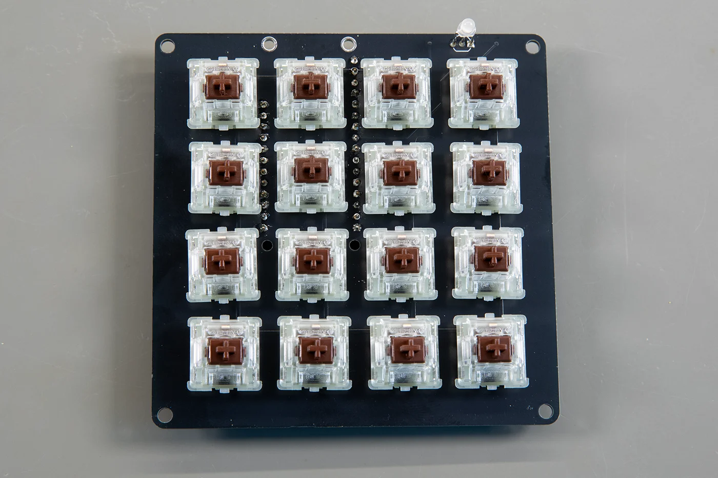
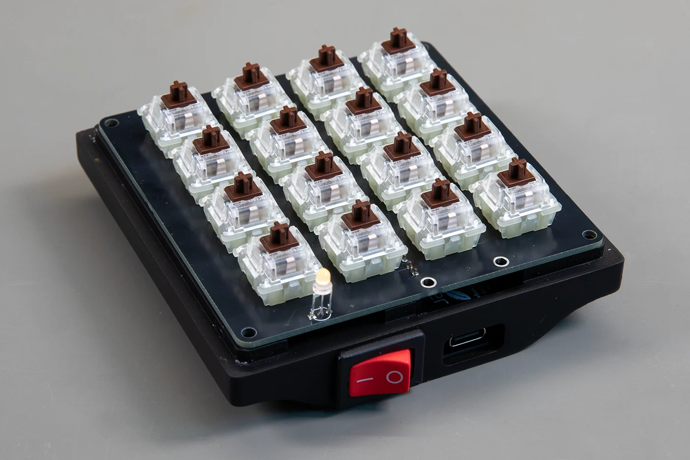
The LED can be installed by placing the LED into the top of the case and pushing the pins through the PCB. When it is flush with the top cover the leads can be soldered to the board.
Install the Feather PCB into the headers.
The battery is fitted to the bottom of the PCB using double sided pads. Make sure the pad is thick enough to stop the pins from the switches breaking through and piercing the battery.
The power switch is clipped into the case base and the red wire on the battery needs to be cut to solder to the switch terminals. You may need to extend one of the wires to enable it to connect to the socket on the feather board.
Insert the battery connector to the feather board.
The top of the case needs the bolt holes to be tapped with a M3 tap.
The case can now be assembled with the PCB held in place with the two case parts.
The M3 x 12mm bolts are installed to secure the case together.
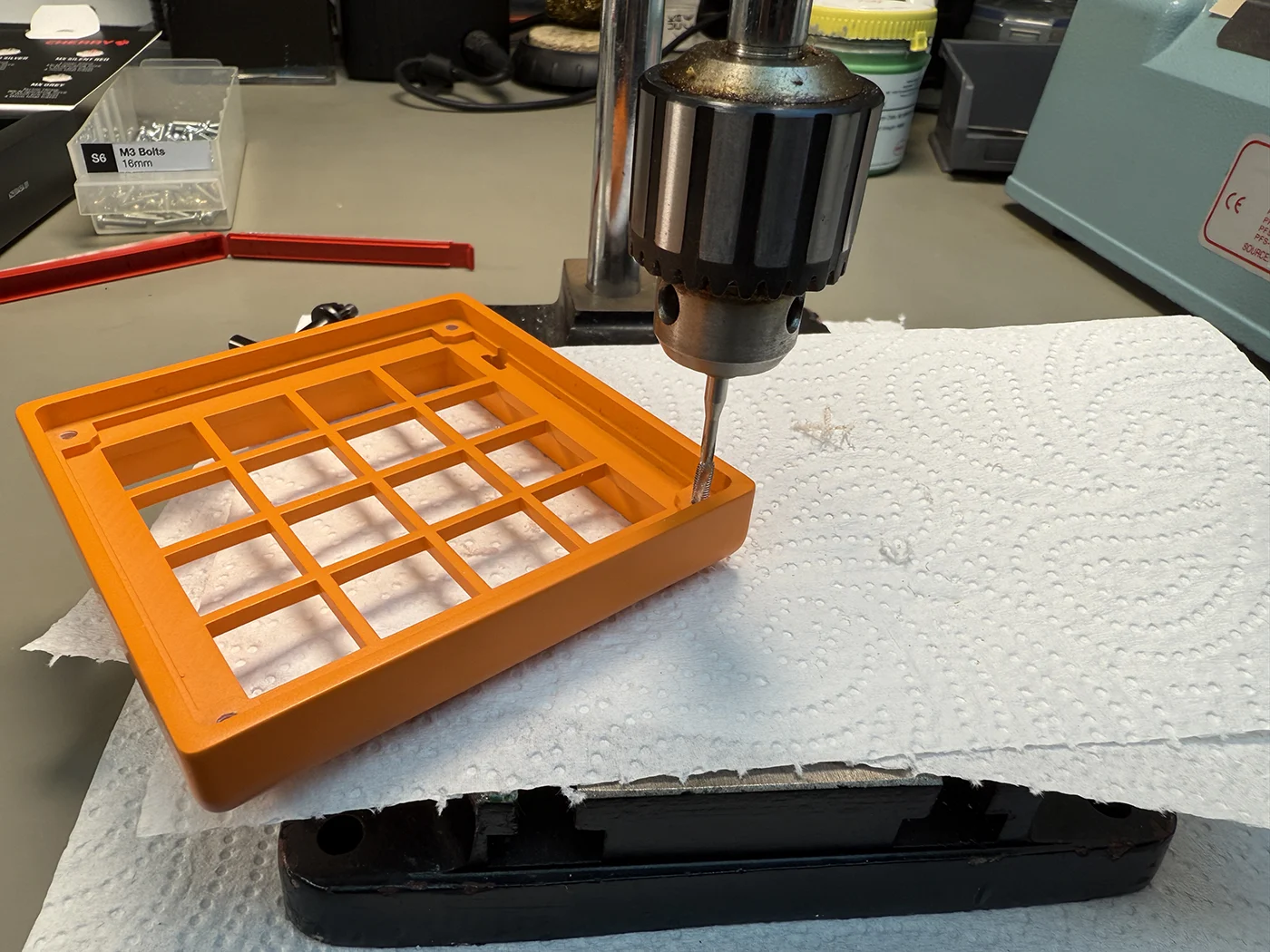
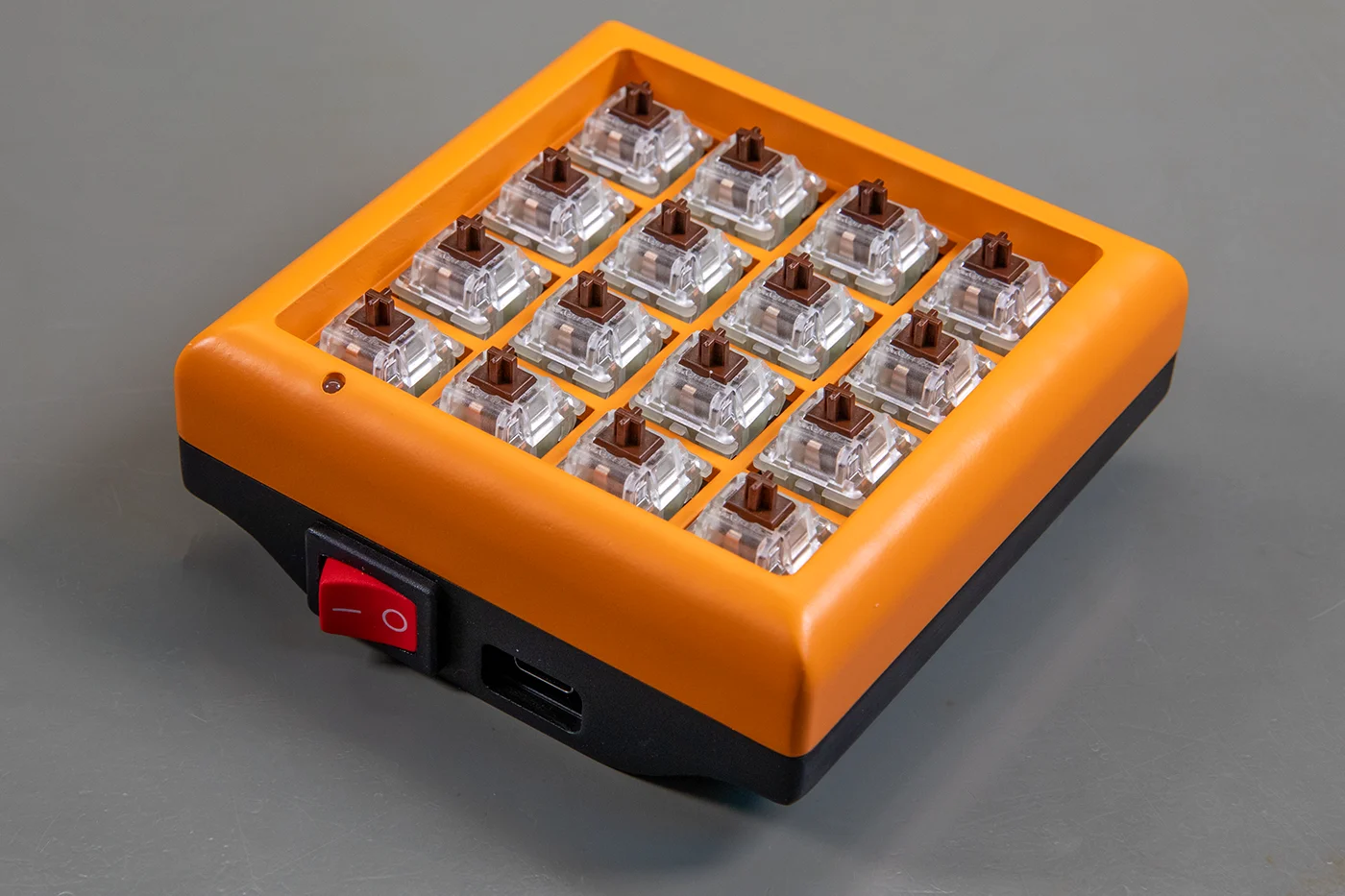
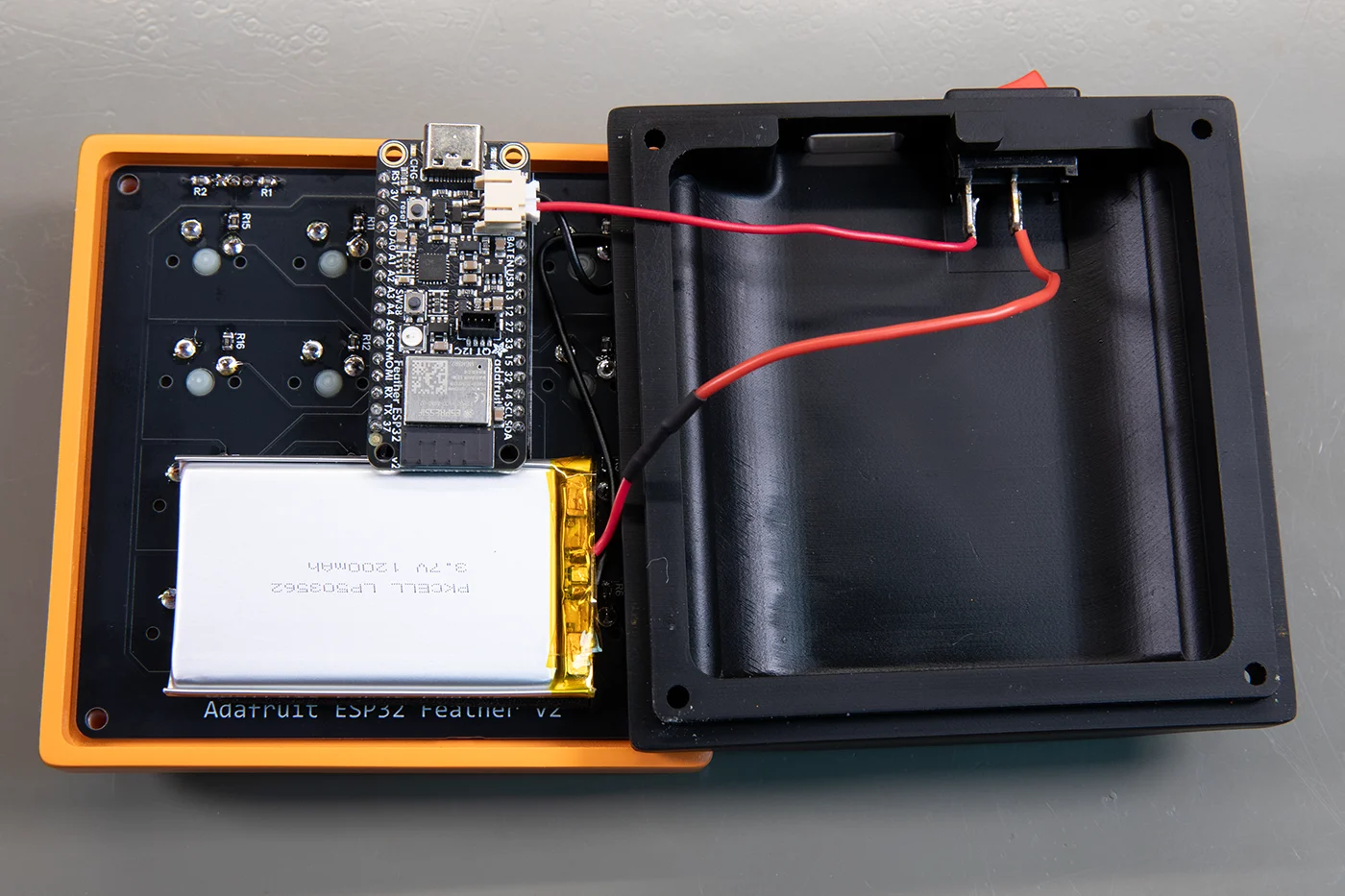
The keycaps can now be assembled. The icon set can be downloaded and printed from GitHub or you can design your own icons for the keys if required.
The keyboard is now ready for the firmware to be installed.
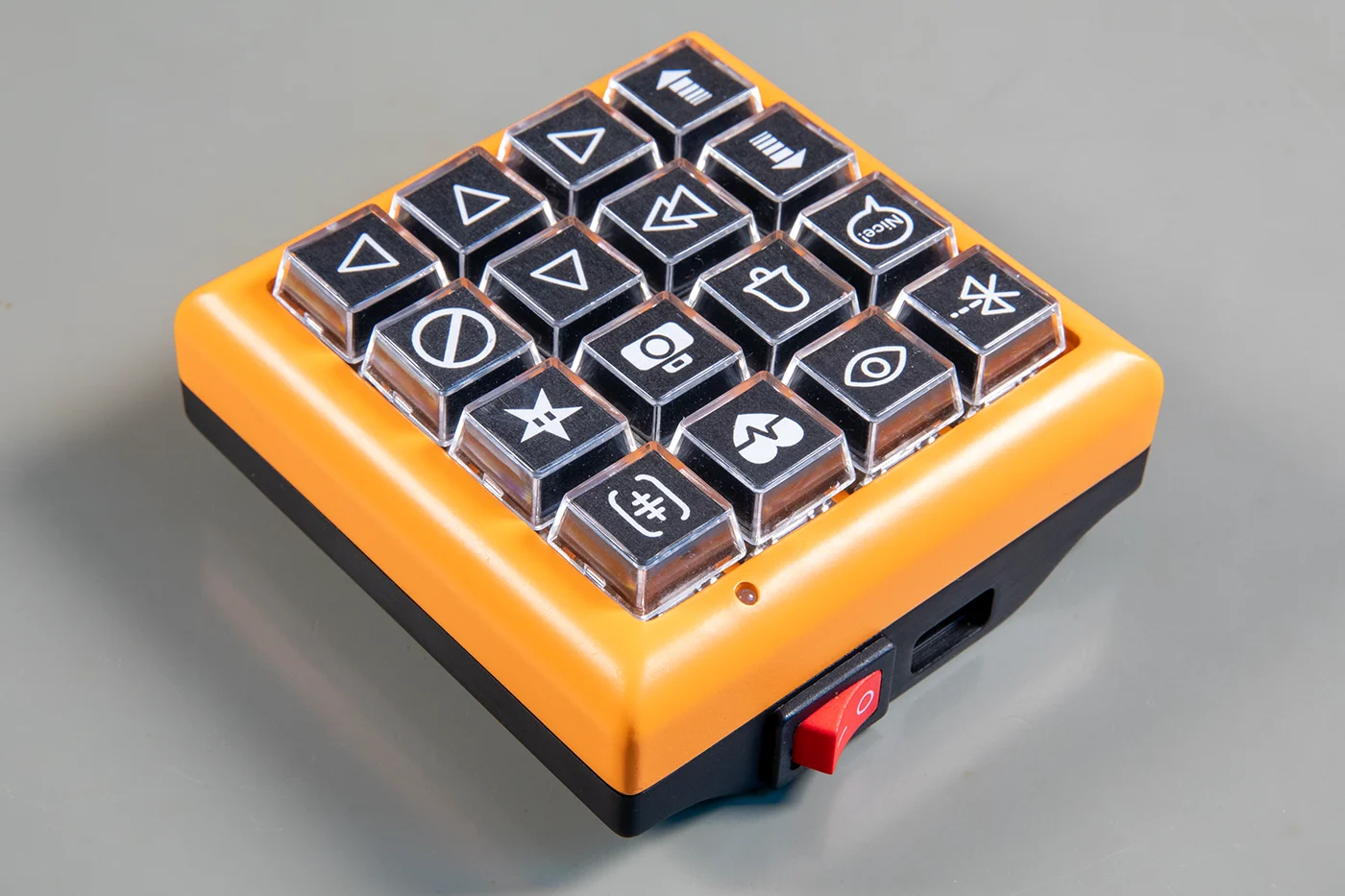
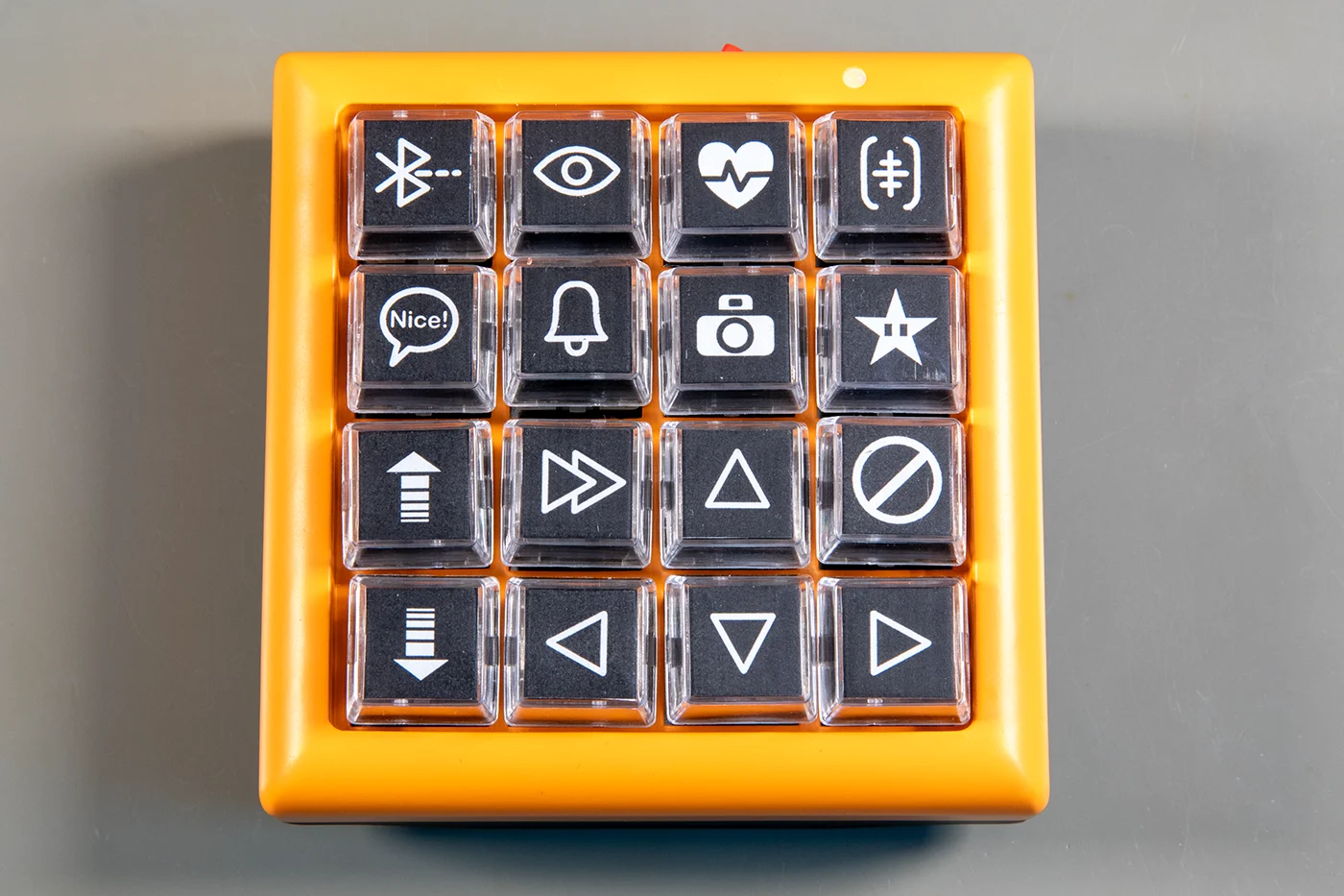
Software
The software was written in C++ using Clion which is a cross-platform IDE for C and C++ from Jet Brains with the platform.io plugin to write the code and program the board.
It uses the BleKeyboard library from github.com/T-vK/ESP32-BLE-Keyboard.
Upon power on the board goes through a setup routine.
The LED pins are set as outputs with the red led turned on.
The key switch pins are set as inputs with internal pull-ups disabled.
A timer is created that triggers every 10 seconds. This sets a flag to update the battery status in the main loop.
A bluetooth keyboard object is initialised allowing the keypad to connect to the computer.
They keypad will show up as a bluetooth keyboard device called “Bike Keypad”.
The main program loop is used to monitor for key presses.
At the start of the loop the flag for the battery status is checked. If the flag is set to true the battery voltage is measured and a battery level percentage is calculated. The battery level is sent to the bluetooth controller where it can be viewed on the computer as well as updating the colour of the LED to indicate the battery status.
The LED shows green if the battery is over 90%, amber for 30% to 90% and red below 30%.
To check for key presses a loop goes through the 16 keys reading their state. If the state is different from the previous loop the program tests to see if the button is high or low. If it is high the current cpu time is stored. If it is low that means the button has been released and the code checks to see how long the keypress was and which key was pressed.
We decided to make the keypad respond on key release instead of the usual key press as this allows the keys to work as different functions depending on how long the key was pressed. If the key press is less than 1 second it is detected as a short press, more than 1 second is a long press.
For most of the keys short or long presses will send the same command to the computer but two keys, the Change View key and the Photo key have different functions for long presses.
On a short press the view key will cycle through the 10 view options in Zwift. These are set on a regular keyboard using the number keys 0 to 9 so on each short press a currentView variable is sent to the computer before being incremented by 1. If the variable reaches 9 it is set to 0. On a long press the view is reset to the default view of 1.
For the camera button a short press triggers the capture still function in Zwift. A long press triggers the capture video clip function.
At the end of the loop function a 50ms delay is added to reduce key debouncing.
The software for this project can be downloaded from GitHub at github.com/briandorey/ZwiftBluetoothKeyboard
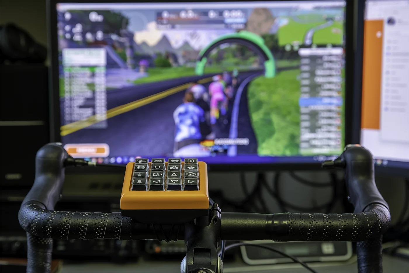
Button Functions
| Row / Button | Key | Long Press |
|---|---|---|
Row One |
||
| Change View | 0 - 9 | Reset to view 1 |
| Watts/HR | g | |
| HUD | h | |
| User Customization screen | t | |
Row Two |
||
| Nice | F5 | |
| Bike Bell | F8 | |
| Photo | F10 | Video Clip F9 |
| Power Up | Space | |
Row Three |
||
| Intensity Up | Page Up | |
| Return/Select | Return | |
| Up Arrow | Up | |
| End Ride | Esc | |
Row Four |
||
| Intensity Down | Page Down | |
| Left Arrow | Left | |
| Down Arrow | Down | |
| Right Arrow | Right | |
Comments