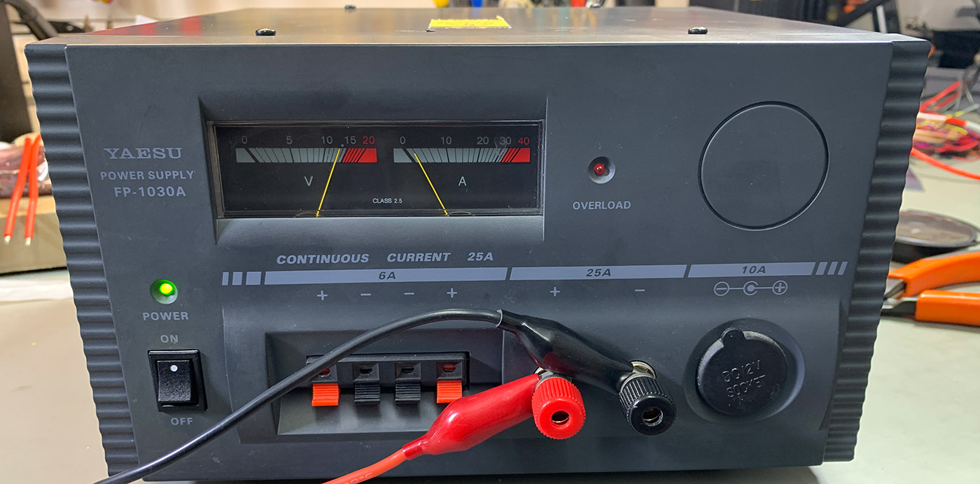
My Yaesu FP-1030A power supply failed with a strange fault where the voltage would fluctuate between 8 and 18 volts when first powered on with a small load connected but without any load, it would start at the correct 13.8 volts. As soon as any current was drawn over one amp the overcurrent protection would trigger turning the power supply off.
It was connected to my Yaesu FTDX 3000 HF radio at the time and the voltage drop made the radio crash and caused the built-in ATU (antenna tuning unit) relays to start clicking randomly.
As the power supply is well outside its warranty period and dates to the early 2000s, I decided to try to track down the fault and repair it.
The power supply is a linear supply with a very large and heavy transformer inside the case and uses a fully analogue feedback regulation system rather than a switching supply which the more compact power supplies use. The benefit of the linear power supply is the much lower electrical noise output compared to switching units.
The Yaesu FP-1030A is rated at 13.8 volt DC at 25 amps continuous with current overload protection at 27 amps.
Finding the Schematic
Yaesu does not supply any circuit schematics or parts list on their website but a search on Google found several PDF files for a technical supplement dated 2003 for the power supply.
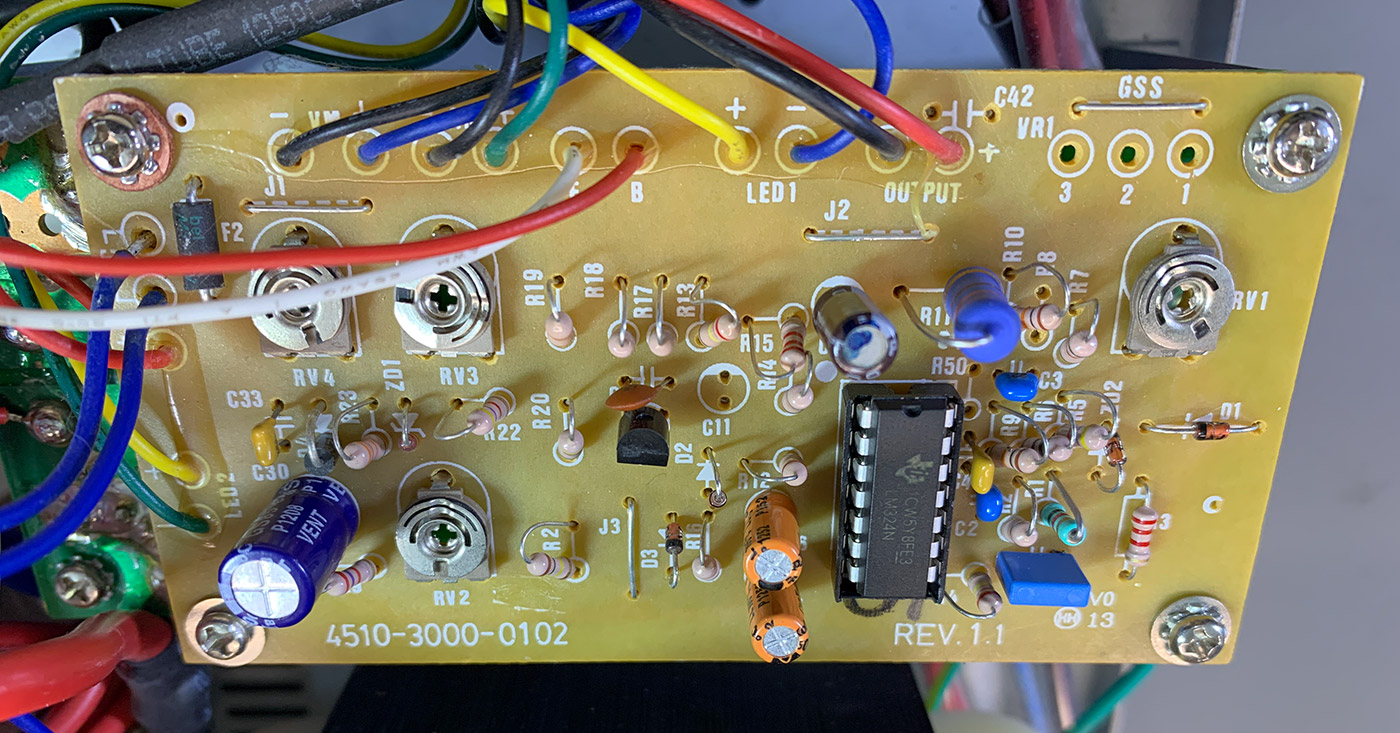
The power supply contains 10 single-sized PCBs which are interconnected with various-sized wires. All the components are through-hole with no surface-mounted parts used in the design.
The circuit uses an LM324-N which is a low-power, quad-operational amplifier. Two of the op-amps are used for voltage regulation, one for current measurement and one for overload protection.
Adjustment of the voltage, overload protection and the analogue meters on the display are adjusted via PCB mounted variable resistors.
A 17-volt Zener diode is used in the overcurrent protection section and a 7.5-volt Zener diode is used in the voltage regulation section of the circuit.
Fault Finding
With the case removed the main regulation and control PCB is located between the transformer and the front panel. It has connecting cables linking to the front panel meters and other circuit boards.
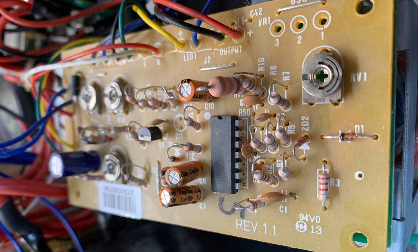
A visual inspection didn’t show any blown components and so we tried the thermal camera which showed a higher temperature on the 330 ohms, 1-watt carbon resistor marked R11 on the board. The schematic shows that this is used across the output and appears to be used to discharge the capacitors when the power supply is turned off. The power dissipation for the resistor should be around 0.6 watts.
This resistor is located at the end of the LM324-N which seemed to have caused the heating of the chip and surrounding components.
We started by replacing the capacitors on the board as these are normally the first parts to fail on older circuits.
This did not resolve the issue and so we removed the LM324-N and installed a socket to make testing new chips easier. We also replaced the 330-ohm resistor at the same time.
The Zener diodes were replaced but after testing the old diodes they appeared to have been working correctly.
With a new LM324-N quad op-amp installed the power supply would not power on which seemed very strange as the new chip was from the same manufacturer and part number as the original.
Found a manufacturing defect
A close inspection of the copper tracks on the PCB under the microscope showed a small manufacturing defect which had a bridge under the solder mask next to the LM324-N, between pin 10 which is input 3+ and pin 11 which is connected to ground.
Checking between the pins on the chip with the multimeter showed a short circuit.
The op-amp connected to pin 10 is the voltage reference used in the voltage regulation and should have been connected to ground via a 1k resistor. The variable resistor which is used to set the output voltage was set very close to the end of its travel and this must have been set at its extremes to compensate for the PCB defect.
As this short circuit has been on the power supply from new it cannot have been related to the new overload issues.
As the internal op-amps which are responsible for the overcurrent protection and also the second stage of the voltage regulation are next to the 330-ohm resistor, we think that the heat from the resistor had caused damage over time and this finally caused the chip to become unstable.
Fixing the faults
We cut the bridge on the track using the Dremel with a small milling cutter and after doing this we installed a new LM324-N the power supply then turned on and the overload issue seemed to be fixed
The output voltage was then adjusted using RV1 to 13.8 which is now closer to its centre point and with the DC load connected we set the current draw to 10 amps and adjusted RV3 to set the amp meter to show the correct current load.
Our DC load can only go up to 26 amps and so we set it to the maximum and adjusted RV2 until the overload protection turned on cutting the power output. With the DC load set to a lower value the power supply then functioned correctly.
We then set the DC load at 5 amps and ran the power supply for 30 minutes and monitored the output voltage with it under load. There was initially a small variance, but we cleaned the variable resistor responsible for the output voltage and after this the voltage was more stable.

Simon
Hi there great reading this article. I have just brought one off eBay and has a continuous power overload light on. I believe this could be the same issue that you also had
Jim Coon
I am a newly licensed General and have purchased a Yaesu FP-1030 Power Supply. Instructions say to "connect a good earth ground to the GND Terminal on the bottom case". I can't find any such terminal. There is one tiny screw that has what looks like an antenna symbol next to it. I don't know how I would get a connector under that tiny thing. Can you help. Thank you so much
Brian
You can use one of the rear case screws to connect a terminal for the earth cable.
Mike
I have one also that the voltage has started fluctuating but the overload light has never come on. I contacted Yeasu about it to see if by now, they might have a better idea of what's causing this to happen but although the tech was nice about it, there are no solutions or information on the problem. It seems as though the internal low voltage op amps are mainly the cause of the voltage instability. I've ordered some with a few extra's for down the road but haven't gotten them in yet. Can someone tell me which op amp is the one that has to do with voltage? Thanks in advance for any help.
Brian
Hello Mike
I am not sure which opamps are used for the voltage. My PSU ran for 10 more months then failed again so i have now replaced it.
Mike
Hello Brian,
Thanks for the information. I'm going to see about getting this one fixed and hopefully it will last longer than 10 months. I've always known Yeasu to stand behind their products but I guess this one isn't worth the effort. Thanks again.
Gary
Regarding:
"We started by replacing the capacitors on the board
as these are normally the first parts to fail on
older circuits."
WHY do this?!? Did you first measure them? Were they shorted
or open? If no signs of obvious failure, no need to replace them,
especially at this stage of troubleshooting. This INSTANT
determination of capacitor replacements without ANY supporting
evidence of component failure is all too often NOT needed! IF
you've got a DC filtering issue (excessive ripple) on the DC
output that is 'one' area to consider - other being the full
bridge rectifier.
What was the 330-ohm resistor measuring? Was it burnt,
discolored, was it within specification (tolerance)?
If it was without visual burn marks and in tolerance, no
need to replace it.
SAME thing with the Zener diodes, they can be tested with
a variable power supply. Again, even with a DMM, if not
open or shorted - they're likely fine. BUT, can check with
an external power supply to see if they're regulating. All
you need to do is lift one leg of the component to do that.
Manufacturing defect? Unlikely. Why? How was it originally
sold new and not working? Even if the 'trace' (you refer
to "copper tracks") was unnecessarily bridged from the
factory after manufacturing the PCB - it would have been
opened prior to test and shipping the power supply. If for
no other reason, the power supply is powered up at the
factory to verify DC output. Did you check the schematic for
those pins.
What you were doing is commonly referred to as, "shot gunning."
Not knowing where the real problem lies, you're just going
to start replacing components out of the blue for no real
justifiable reason. That's time consuming and certainly can
be expensive.
Once you become experienced and understand the circuit
a bit better (beforehand) you'll be able to zero in on issue
without arbitrarily and unnecessarily replacing working
electrical components.
Consider: In the future, if possible, measure a good non-modified
FP-1030A voltages at various components in the power supply and
PCB and mark that on your schematic for future reference. If
anything goes awry in the future, you'll be able to compare and
contrast those measurements with your current condition.
Good luck!