One of my hobbies is Amateur (Ham) radio and it is useful to be able to check the outputs on the radios transmitters to check that the signal is transmitting on the correct frequency and not causing spurious frequency problems.
It isn’t safe to connect the output of a radio directly to a frequency counter or oscilloscope due to the high voltages and currents on the transmitter and so we needed a way to sample part of the transmitted signal while dumping the output into a 50-ohm dummy load resistor.
After researching various options and commercial products we decided to build a variable RF signal sampler so we can use an attenuated signal from the radio's main TX output.
An RF signal sampler works using capacitive coupling between the signal you wish to sample and the sample output which can be connected to an oscilloscope or spectrum analyser. The air gap between the output to the oscilloscope and the pass-through rod acts as a variable air-spaced capacitor attenuating the signal to a level suitable for measuring.
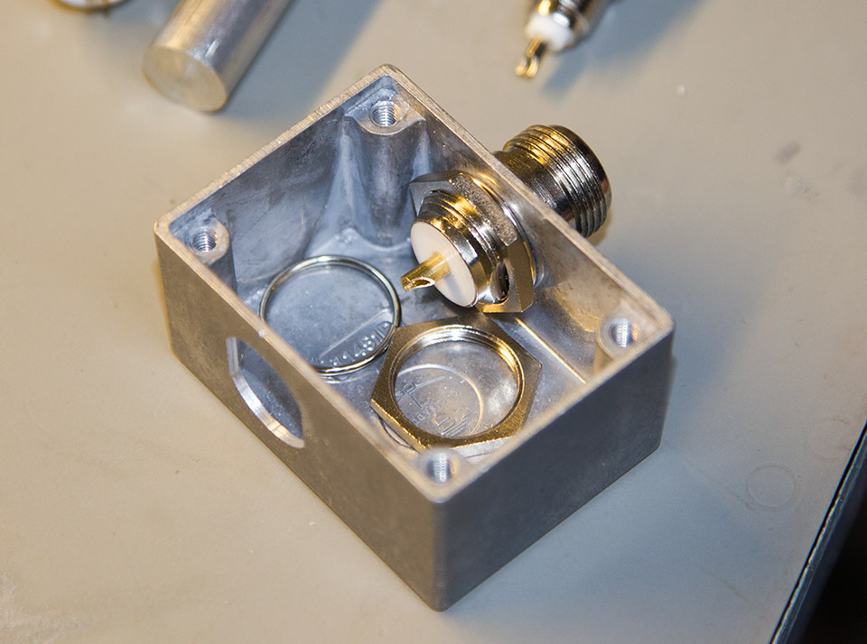
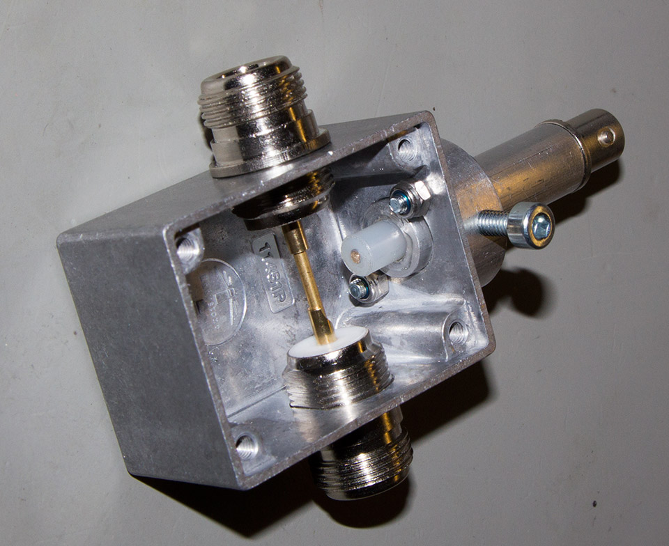
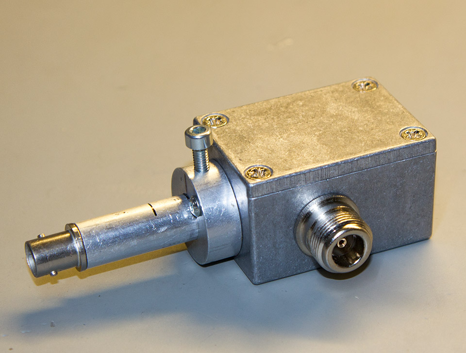
We built the sampler using a diecast aluminium enclosure,52x38x27mm RS Stock No 3439861 and used a pair of N connectors for the pass-through port.
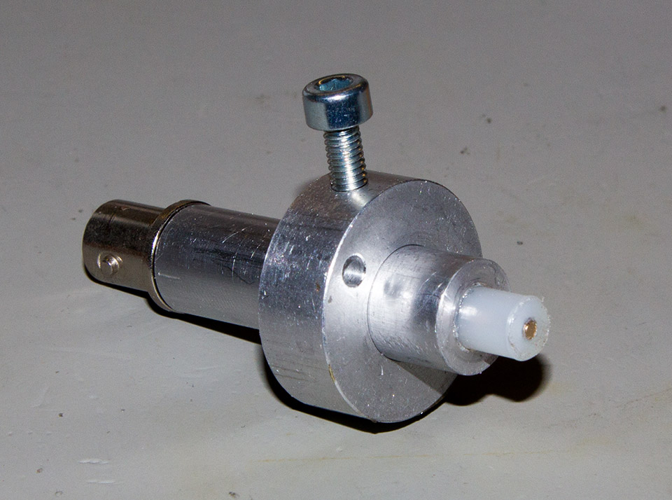
On the end of the box, we fitted a 10mm thick aluminium disk with a 12mm hole in the middle to accept a 12mm aluminium rod as the adjustable output.
The aluminium rod had a 6mm hole drilled down the middle and one end was threaded to accept a BNC socket.
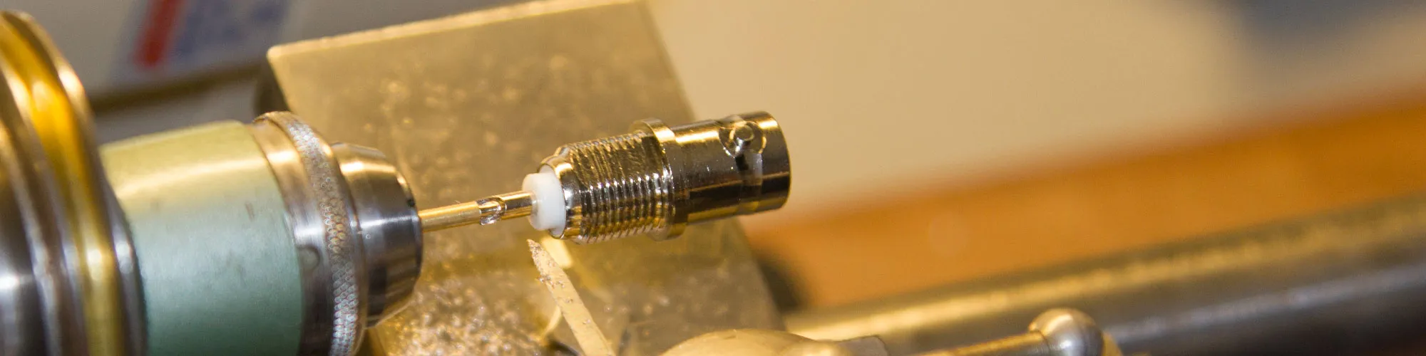
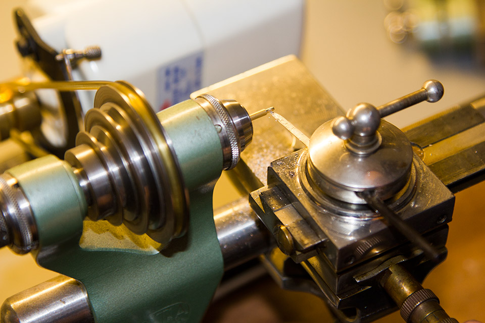
A short length of 2mm brass rod was trimmed on one end of the lathe to fit into the centre conductor of the BNC socket and this was then fitted into a piece of 6mm nylon rod which was then fitted into the 12mm aluminium rod.
This was then fitted into the end of the box and is held in place with an M4 bolt to allow the distance between the centre conductor and the RF input/output bar to be varied to change the attenuation between the transmitter's output and the counter/scope input.
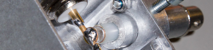
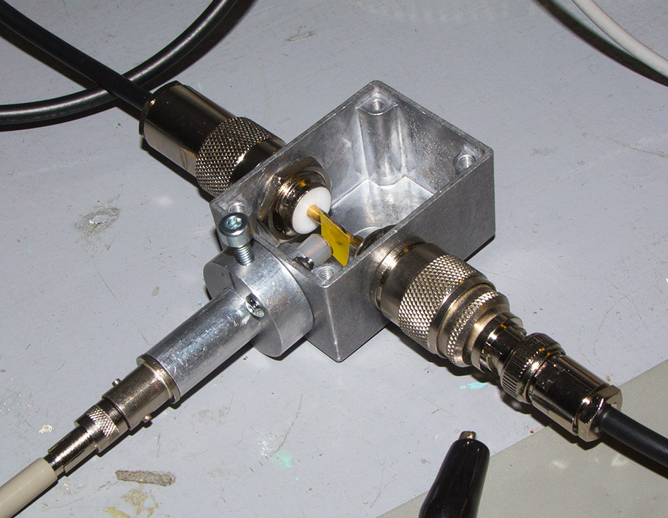
Initial tests with the 2mm rod conductor showed a very high attenuation of over -80db and this was too high to get reliable measurements. We then fitted an M2.5 brass washer to the end of the adjustable section and a matching one on the crossbar between the two N connectors.
An insulator was then fitted on the brass washer to stop both ends short-circuiting and redirecting the RF power into the sample port. A small piece of sticky insulation tape was used to keep the contacts apart.

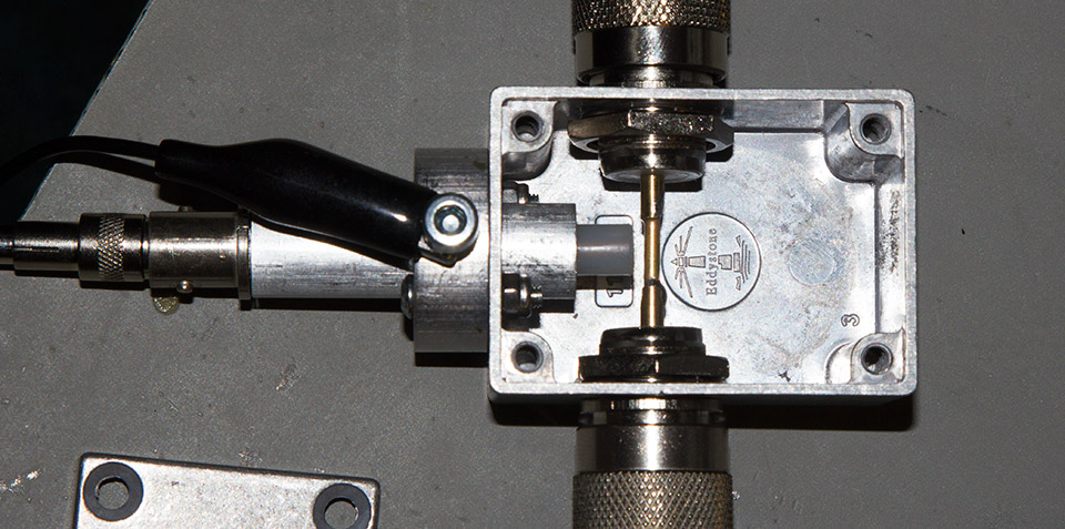

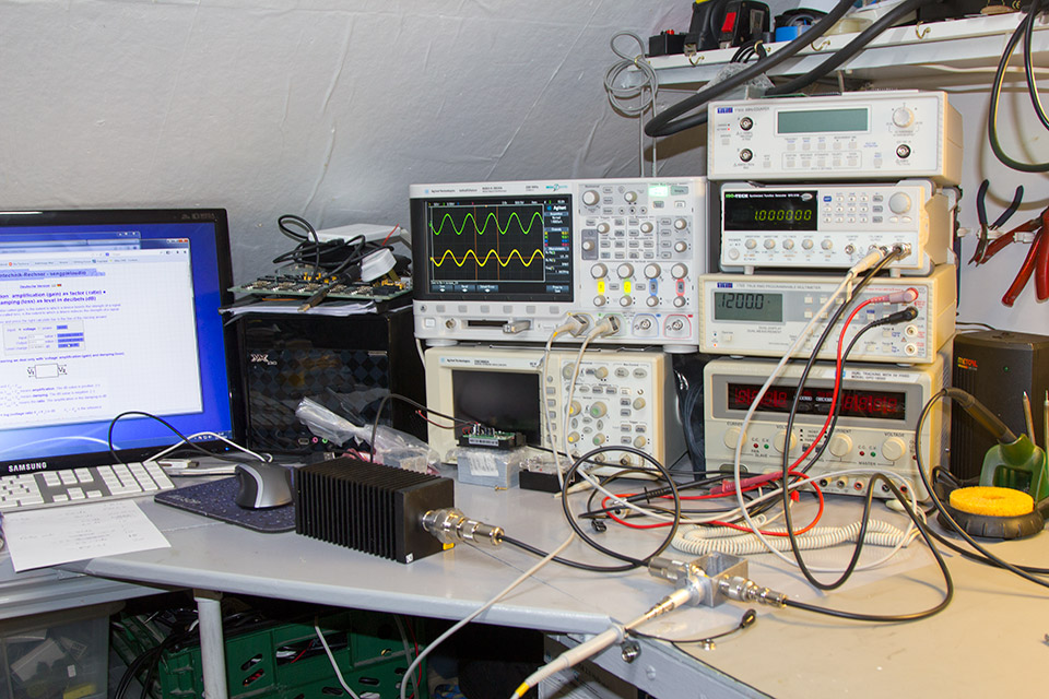
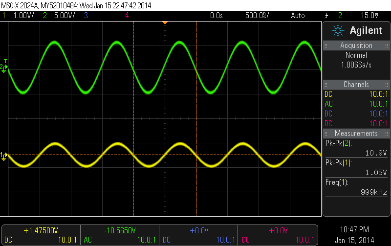
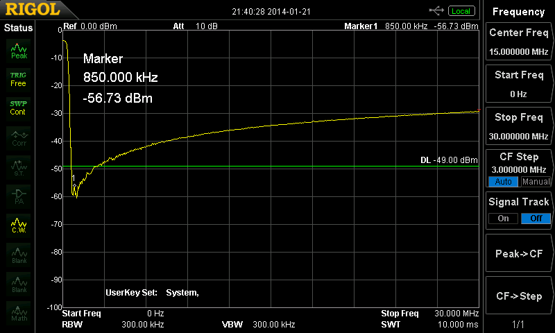
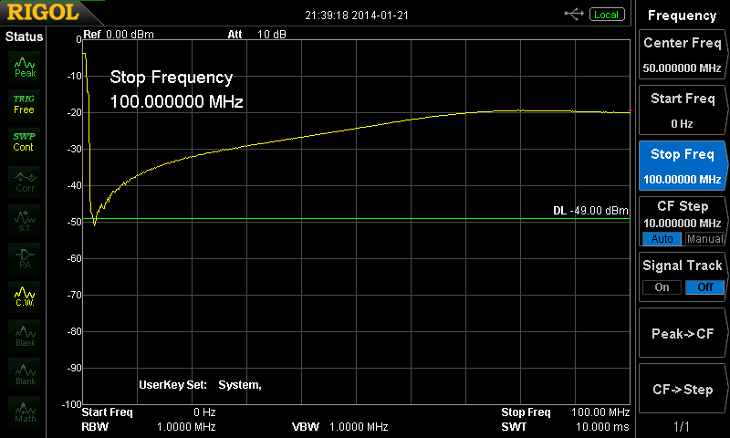
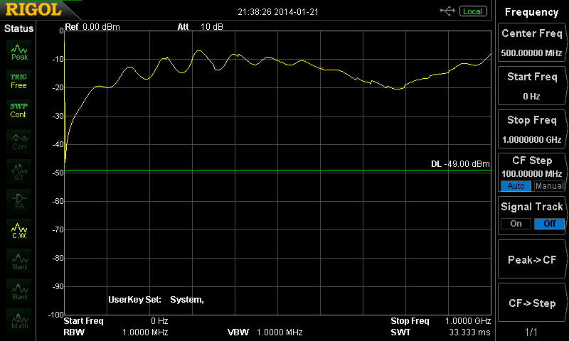
The unit was then tested using a 30Mhz signal generator and the output was monitored on our MSO-X 2024A oscilloscope on frequencies between 1Mhz and 20Mhz.
The attenuation with the adjustable section fully in varied between -20db to -31db and with the adjustable section fully retracted measured between -51db and -58.5db.


joseph carragher
Build a ISO TEE use a T connector. Pull the centre pin out cut the pin so when u put it back in place its flush with the insulator. screw on a barrel connector for separation and job done that's my rf sniffer
Tony
Great idea. I will start building a copy of your RF sampler design tomorrow except that I will machine the sampling rod so that the tip cannot reach the feedline, or even simpler, slide a piece of plastic sleeve over the feedline. Also planning to include a RF Ampmeter in the one I build. 73 de KD4MRS