Our ongoing solar data logger project is making steady progress. A crucial part of this project involves using Atmel-based slave boards to measure various sensors positioned throughout the house. These boards are interconnected via a full-duplex RS485 network, ensuring reliable communication.
Initial Setup and Debugging
We initially designed a full-duplex RS485 board for the Raspberry Pi to facilitate communication with these sensor boards. However, for easier debugging and versatility, we decided to use a USB device on a PC or Mac.
Need for a Full-Duplex Adapter
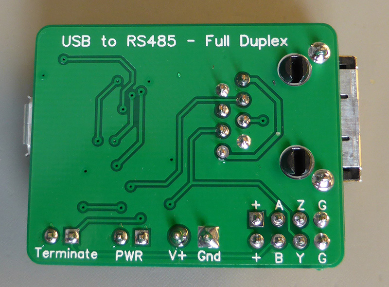
While searching for a suitable full-duplex adapter, we found that available options were limited to half-duplex devices. Additionally, our requirement to supply 12 volts through RJ45 connectors on the slave boards led us to design our own USB to RS485 full-duplex adapter using an FTDI USB converter chip.
Design Features
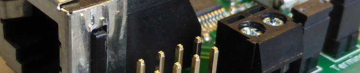
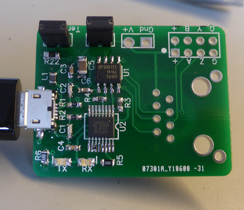
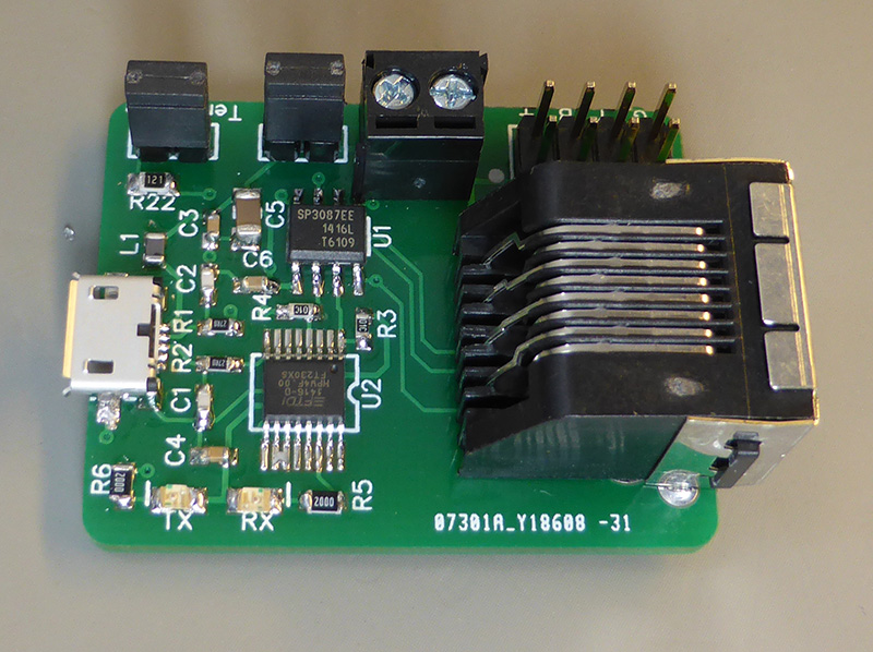
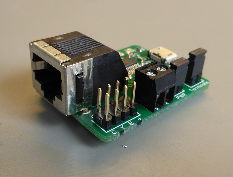
- FT230X USB Converter Chip: Our adapter utilises this chip from FTDI, paired with an RS485 converter chip. The output is available via header pins and an RJ45 socket.
- Power Supply Flexibility: The board can draw power from the USB port or an external supply, selectable via a power jumper.
- Onboard Terminator Resistor: A 120R terminator resistor with a selection jumper is included.
- Activity LEDs: These indicators show serial communication activity, aiding in debugging.
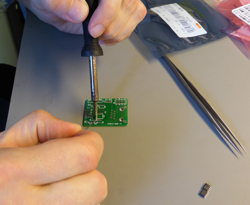
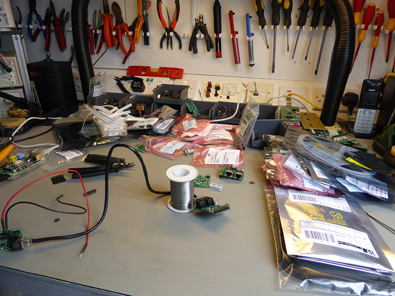
Assembly and Testing
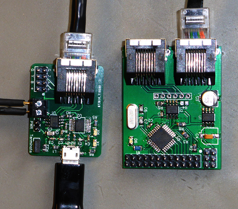
After soldering the necessary SMD components and fitting the RJ45 and header pins, we tested the adapter with the Atmel interface, to confirm everything was functioning correctly.
Downloads
The PCB files and schematics for this USB to RS485 adapter are available for download on GitHub. This allows for customisation and further development by other users.

Sebastian
Hi Brian
nice rs485 pcb :)
i tried to import this to kicad but did not get any holes for the components, also no schematics, do you have more files for this somewhere else?
kind regards
Sebastian
Brian
Hi Sebastian
You can open the files in Diptrace which is free from
https://diptrace.com/download/download-diptrace/
You should then be able to export them to different formats for kicad.