For the past few months, we have been working on a set of new USB smart chargers which run from our off-grid 12V system to be used for charging tablets, smartphones and other devices which charge from a USB port.
The aim of the new smart chargers was to have the following features:
- Current monitoring
- Voltage monitoring
- Data Logging
- Low voltage cut-out mode
- Device detection
- Connection to our solar logging system using either a wired or wireless connection.
After looking at various ways to communicate with the USB charger boards we decided to use Bluetooth LE (Low Energy) as this had the best options for ease of use and power consumption compared to using a WiFi module or adding serial communications and associated wiring throughout the house.
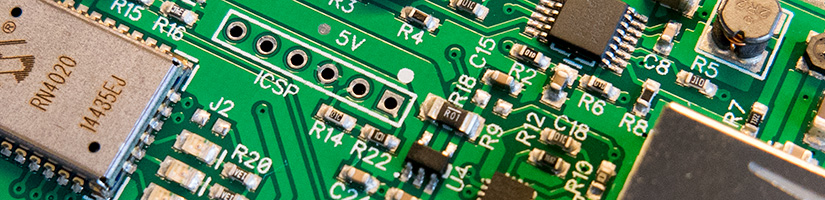
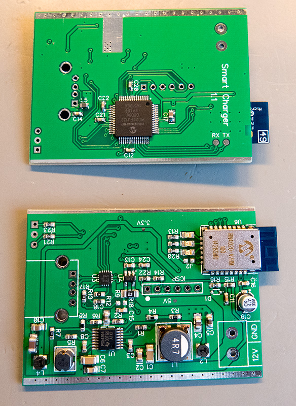
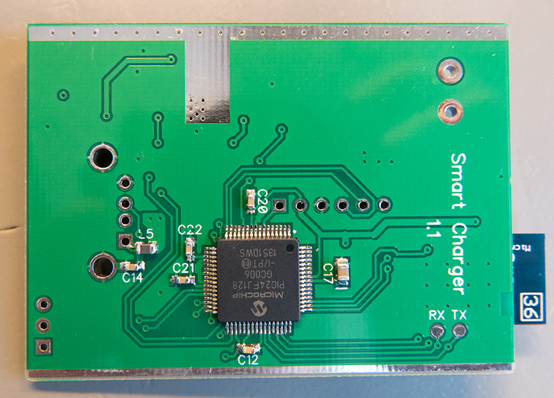
The design is based on a Microchip PIC (PIC24FJ128GC006) which is used for the management of the charger and this communicates with the RN4020 Bluetooth module via UART for the data logging sections of the design.

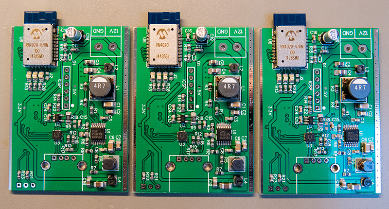
The previous USB chargers that we designed used a linear power supply to drop the voltage from 12V to 5V. The problem with linear supplies is they waste a lot of power with most of the energy being converted to heat rather than charging the USB device. For the new design, we decided to use switching power supplies with a high current 5V supply for charging and a lower current 3.3V supply for the control system.
The 3.3V and 5V switching power supplies are based around the TPS54394 3A dual switcher IC from Texas Instruments. The 3.3V supply powers the PIC microprocessor and Bluetooth module while the 5V supply is for the USB charging at up to 2 amps.
The microprocessor uses its internal 16-bit ADC to measure the input voltage from the solar batteries through a voltage divider and this has a low voltage cut-out threshold programmed into the code to disable the 5V power when the battery level is too low. The charger will only resume charging once the input voltage reaches a pre-set voltage threshold.
The second 16-bit ADC channel monitors the current going to the USB device via a current-sense resistor and a TS1100-100 precision current-sense amplifier to determine the current being drawn by the device being charged.
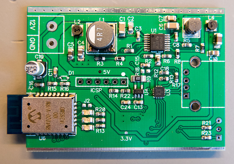
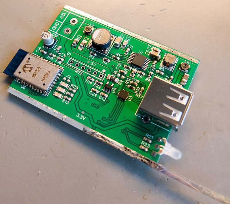
To control the USB charging we used a TPS2540 charging controller from Texas Instruments. The TPS2540 connects between the USB device and the microcontroller and automatically negotiates the charging rate when a device is plugged in so any phone or tablet will charge at its maximum current rate.
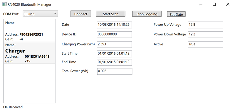
The RN4020 Bluetooth module from Microchip communicates with the microcontroller via UART and can support up to 10 private services alongside the standard Bluetooth LE services. We designed the charges to use 9 of the private services for controlling and monitoring the various functions. The services that are available include:
- Date and time of the internal RTC
- Active state of the charger
- Current power usage of the device being charged
- Total power usage in watt-hours for the current device
- Charging Start Time
- Charging Stop Time
- The USB VID and PID for the current device
- The power-down voltage threshold
- The power-up voltage threshold
When a USB device is detected by the microprocessor the ID of the device is logged and the start time and the processor send this data via Bluetooth LE to the central data logger on the Raspberry Pi which will then be sent to our online home logging system.
The processor continually logs the current being used and when the device is charged or disconnected it then sends this information back to the data logger to show how much energy the device took to fully charge.
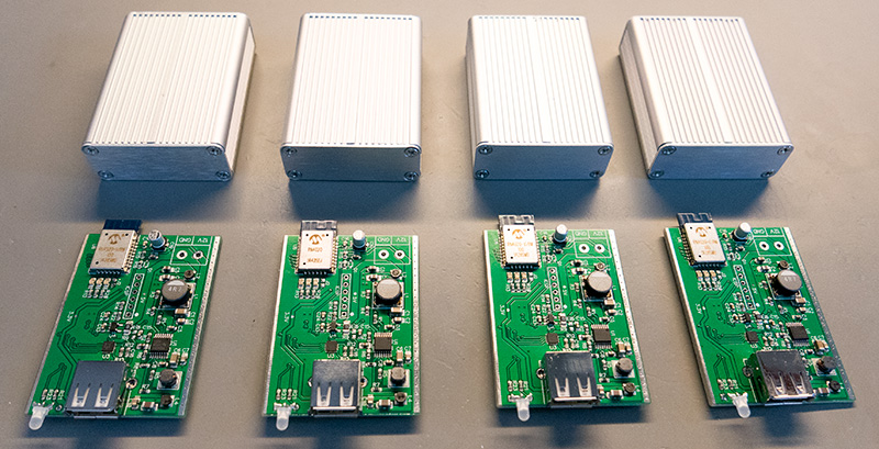

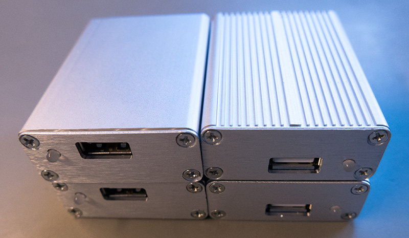
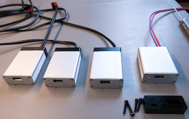
We found some aluminium cases on AliExpress which we used to enclose the chargers. The switching power supplies generate a small amount of heat when they are running so we designed the PCB to transfer the heat to the edge of the board where it comes in contact with the case so the case acts as a heatsink keeping everything cool. The front panel was machined on our CNC mill to cut a hole for the USB socket and an LED. As aluminium cases are good at blocking RF radiation we put the Bluetooth module at the back of the PCB with the antenna overhanding the rear edge of the case. We then cut a new back panel out of plastic so the RF would not be blocked and the Bluetooth module can connect with the client.
An LED on the front panel is used to show the status of the USB charger. When the charger is first connected to the 12V supply the LED glows red to show the charger is booting. Once the Bluetooth module is configured and advertising to any nearby clients the LED will flash green three times. When you plug a USB device into the charger the LED will glow green while the device is drawing more than 100mW and will go out when the power draw drops below this threshold to indicate that the device is charged.
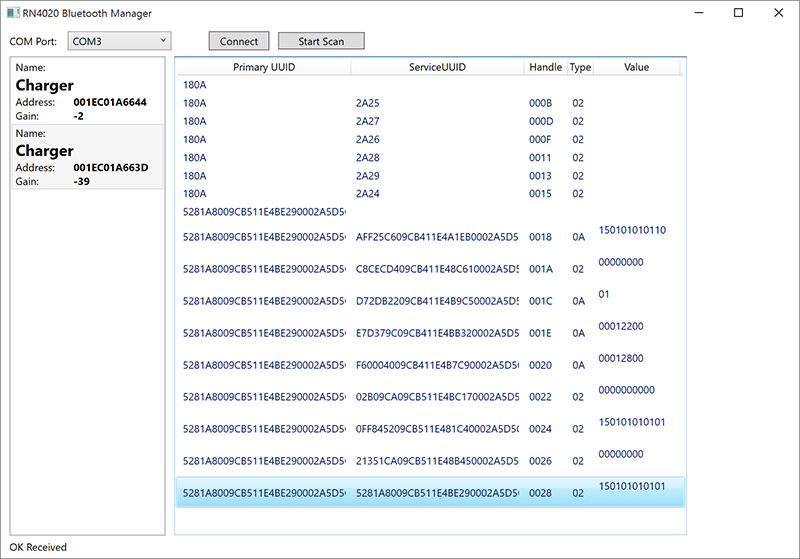
The pcb layouts, circuit information, firmware and Windows demo logging app can be downloaded from https://github.com/briandorey/USB-Smart-Charger-with-BluetoothLE
george
USB Smart Charger with Bluetooth LE how much a euro cost ????