In a previous blog post, we used a Raspberry Pi to set up a monitoring system for our Solis PV inverter. This has worked well for the past 5 months, but we now need a Raspberry Pi for another project. As they are tough to find, we decided it would be an excellent opportunity to replace the solar-logging Raspberry Pi with something simpler and more energy efficient.
After looking at the options available, we settled on using an ESP32 WiFi module as a bridge between the Modbus interfaces on the Solis inverter and energy meter and the MQTT broker on our home server, which runs Home Assistant to log all our smart home data.
Hardware Design
The design would consist of four modules. The ESP32, an RS-485 interface, a temperature sensor for measuring the ambient temperature near the inverter and a light sensor so we can check if the lights have been left on in the room where the inverter is installed.
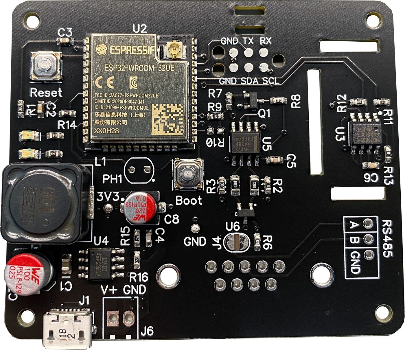
For the ESP32 module, we used an ESP32-WROOM-32U which uses an external antenna. When we first installed the Raspberry Pi, we intended to use the built-in WiFi to connect to our server, but after testing, we found that the signal strength was too low to get a good connection. The 3 metres of concrete between the Raspberry Pi and the WiFi router probably didn't help. By using the ESP32 module with the antenna socket, we could use an external high-gain antenna to provide a better WiFi router connection.
The RS-485 module uses an SN65HVD72D transceiver from Texas Instruments. This is the same chip we use on the RS485 Pi development boards that we sell so that we can copy the schematic from the RS485 Pi with a few minor modifications like component sizes and 348R pull-up and pull-down resistors on the RS-485 bus.
The temperature sensor uses an MCP9803-M/SN from Microchip. This is an I2C-based 12-bit digital temperature sensor that we have used on several other projects, so we have a good supply of the chips.
For the light sensor, a photoresistor was used alongside a 1 megaohm resistor to create a voltage divider. This was connected to one of the ADC inputs on the ESP32, so the voltage would rise and fall with different light levels. Using this approach, it would be easy to set a threshold light level for when the light in the room is turned on and off.
We decided to use the existing 5V USB charger to power the circuit, which powered the Raspberry Pi. As the ESP32 module uses 3.3V, a switch-mode power supply was added to drop the 5V down to 3.3V. After looking at the switch-mode ICs available to buy, we chose the ST1S40IDR from ST. The ST1S40IDR has a 3A output current and can take a 4.0V to 18V input, allowing us to power the circuit from higher-voltage power supplies if needed.
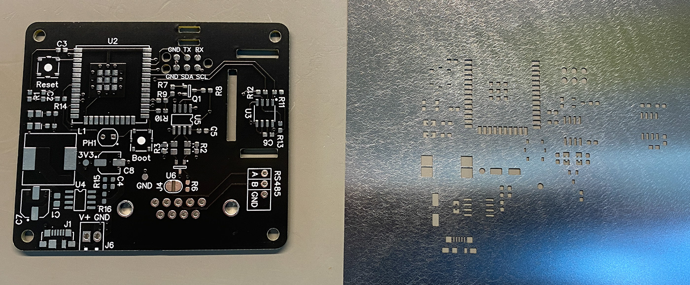
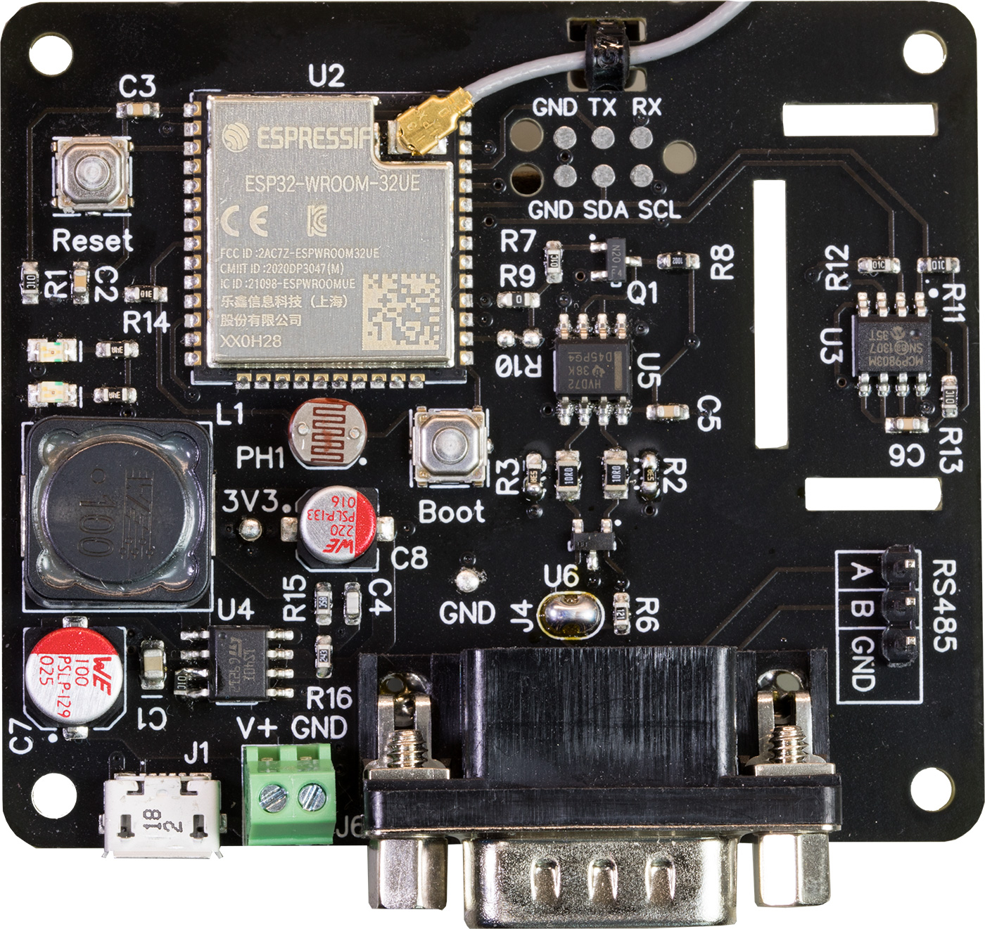
We decided to use the existing DIN rail Raspberry Pi enclosure for the new project, so the whole circuit was designed to fit within the size of a Raspberry Pi hat. A USB micro socket was used for the power supply and was positioned in the same location as on a Raspberry Pi so it would align with the existing hole in the enclosure. A 2-pin screw terminal was also added for the power input to allow us to use wires instead of USB if needed. A 9-pin D-sub connector was used for the RS-485 bus allowing a simple swap with the RS485 Pi used on the existing Raspberry Pi setup.
To increase the temperature sensor's accuracy, the PCB was designed with cut-outs around the sensor IC to reduce thermal bridging with the ESP32 module. The sensor was placed at the bottom of the board with cut-outs in the enclosure below and above the sensor, so air convection would bring outside air in the past the temperature sensor first before the ESP32 module could heat it. After testing, we found that this approach gave a temperature reading almost identical to the external 1-wire sensor used on the Raspberry Pi design.
Test points were added around the PCB to allow testing of each section, and programming pads were added so we could use a new pogo pin connector designed for this and future projects.
After designing and building the board, we found a small mistake with a missing pull-up resistor on the PSU enable pin. This was fixed by soldering an 0603 10K resistor between pins 3 and 4 on the IC. The schematic and PCB Gerber files available to download in our GitHub repository include the fix for this error.
Apart from this mistake, the circuit worked well without needing other modifications.
Software Design
The software for the project was designed in Visual Studio Code using the Platform IO plugin. External libraries were used for the MQTT client, Modbus and Software Serial interfaces.
The software flow is fairly simple. On boot, a WiFi connection is established, an MQTT connection is made to our server, and a hardware timer is started at a 1-minute interval.
On each timer tick, the program first checks that the WiFi and MQTT connections are still active, and reconnection is made if necessary. Next, the temperature is read from the sensor and published to the MQTT broker. Data is then fetched from each register address on the energy meter, and the values are formatted and published to the MQTT broker.
The solar inverter goes to sleep at night, so before fetching the inverter's register values, a test connection is made to check if the inverter is awake. If it is online, the register values are fetched and published for all relevant data, such as power output, PV voltage, current, and device temperature. If the inverter is offline, zero values are published for most of the registers.
Measuring the light level was done in the main program loop instead of inside the timer event. This allows any changes in light level to be detected immediately and posted to the MQTT broker. By adding an alert event into Home Assistant, we can use this as a rudimentary fire/burglar detector, working alongside the existing smoke detector, which is situated close to the inverter.
To make software development easier, we designed a Modbus emulator on a Raspberry Pi, which consisted of a python script that creates a Modbus slave device with the same register addresses and values as the real energy meter and solar inverter.
Installation and Testing
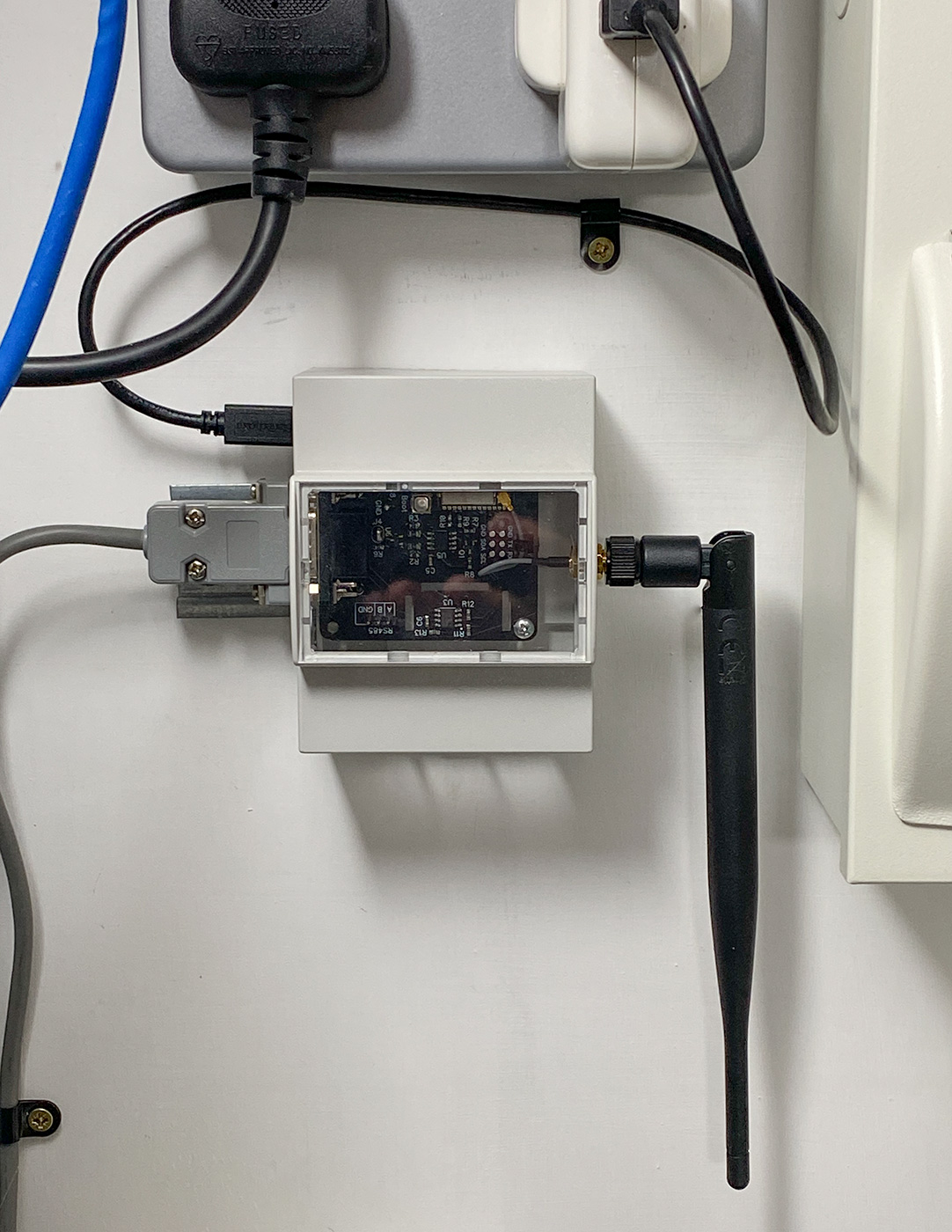
With the hardware and software complete, we fitted the new device in the existing enclosure alongside the solar inverter. After plugging it in and connecting the RS-485 cable, we found a couple of bugs in the code where 32-bit registers were being read in the wrong byte order, but everything worked as expected.
Some power measurements were made to compare against the old Raspberry Pi setup, and we found that the new ESP32-based design uses between 0.2W and 0.5W when running compared to the 2 to 5W of the Raspberry Pi.

SimonR
Thanks for developing this - it looks just what I've been hoping for.
I take it you're planning on commercialising this as a product, as the Git repository is empty?
If so, can I join the queue to buy one?
I've spent the last few days trying to control the inverter via the cloud API from an ESP32 - but finding it's very flaky! My plan was also to write an MQTT bridge.
After too much playing, I'd concluded that the whole cloud interface was best avoided - and connecting to the MODBUS interface might make more sense - get rid of the middle-man.
Although I run HA, my plan was to have another ESP32 driving a set of traffic lights which the household could use as a guide to when is a good time to run the dishwasher for example - based on the battery SoC, Solar Forcast and Agile Pricing and make it stand-alone from HA.
Brian
Hello SimonR
Thank you for your message. It appears I forgot to upload the files to github!
They have been uploaded now and you can download the files.
Brian
DavidM
Thanks for writing up and sharing Brian.
I have a Solis S6 hybrid inverter and am looking to do some local logging and control. Currently all done via the SolisCloud which is pretty unsatisfactory (5 min resolution, in a computer I do not control etc)
Does this completely replace the SolisCloud dongle or does it plug into the separate Modbus port on my inverter ? I'm thinking there can only be one modbus master (the dongle) so this would need to replace it, the other port just being a way to chain multiple inverters together. Does this sound correct ?
Brian
This completly replaces the SolisCloud dongle, I dont know if its possible to daisychain them together