After damaging the GPIO port on our raspberry pi while designing a new solar monitoring system we decided that it might be a good idea to build a buffer/level translator to protect the GPIO pins from overvoltage and ESD spikes. The board would need to protect all of the data pins we normally use which are i2c, SPI and UART, it would also need to work at all of the data rates that those pins can support. Protection for the other GPIO pins would also be useful in case we want to connect anything directly to the Raspberry Pi without using a serial bus. Support for 5-volt logic would also be a bonus as some of the devices we use do not support 3.3V.
All of the major IC manufacturers sell level translators and buffer ICs so after comparing several different devices I decided that the TXS0108E from Texas Instruments would do what I needed. The TXS0108E is an 8-bit bidirectional voltage level translator designed for open drain and push-pull applications, it supports data rates up to 60Mbps and has built-in ESD protection. It can translate between 1.2 V to 3.6 V on port A and 1.65 V to 5.5 V on port B so connecting port A to the Raspberry Pi would allow me to connect 3.3V or 5V devices to the Raspberry Pi. The Raspberry Pi has 17 GPIO pins so two of these ICs would protect all but one pin. GPIO23 is only used as an SD command signal so that one could be left disconnected.
The schematic below shows the design for the buffer board. The two TXS0108E ICs are connected to the Raspberry Pi GPIO pins on one side and a header connector on the other. 100nF decoupling capacitors are connected to the power pins on the ICs and ESD protection diodes were fitted between the Raspberry Pi power lines and ground. Poly fuses were used on both the 3.3V and 5V rails to protect the Raspberry Pi against short circuits.
Click the image for the PDF version
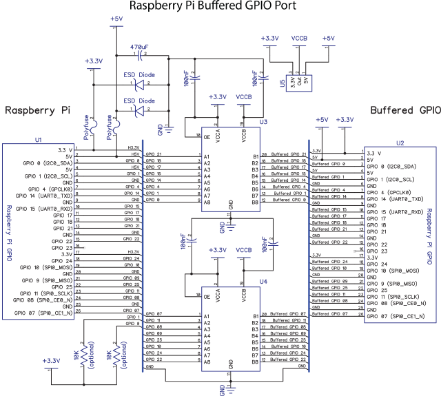
When we first developed our ADC Pi development boards we found a problem with testing them on the Raspberry Pi. The ADC Pi has two 10uF smoothing capacitors and plugging the board into the Raspberry Pi when it was switched on would cause a voltage drop as the capacitors charged, this would in turn reset the Raspberry Pi. To get around this a 470uF capacitor was fitted into the buffer board, this would store enough energy to allow the capacitors on the ADC Pi to charge without dropping the voltage on the Raspberry Pi.
In order for the buffer board to the used with 3.3V and 5V logic, a jumper was fitted allowing you to select the voltage level on the buffered port.
According to the datasheet for the TXS0108E the i2c lines would not need pull-up resistors as this was built into the IC but just in case it did need some form of pull-up we added space for a pair of resistors to be connected between the i2c lines and 3.3V. Once the board was built we found that these were not needed and the buffer worked fine with the internal IC pull-ups.
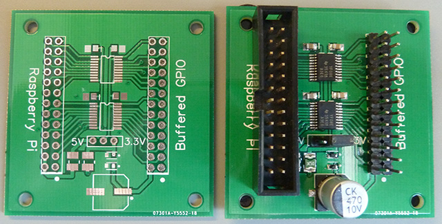
A PCB was designed in DipTrace using surface-mounted parts for all of the components and 2.54mm pitch headers for the GPIO and buffered IO ports. All of the power and ground lines are connected, the only pin which was left unconnected was GPIO23. We chose iTead Studios to make the PCBs, we have used them before and the price for small quantities is far cheaper than our usual PCB supplier. They can make 10 boards at 5cm x 5cm for $9.90 plus postage so the PCB was designed to be 5cm square, this was bigger than the circuit but it would give some extra space for some rubber feet on the bottom and for holding the board still when we are plugging connectors into it. With the design complete the PCBs were ordered and 2 weeks later arrived from China.
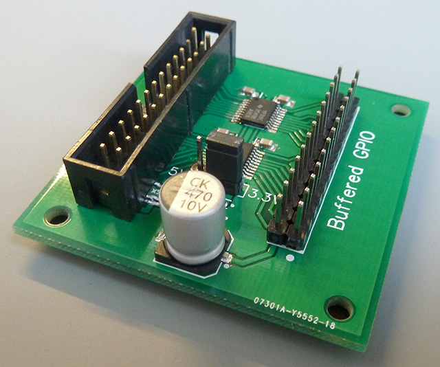
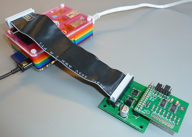
As we didn’t have a stencil for the PCB so a syringe was used to place solder paste on the board and the components were placed by hand with tweezers. After a quick cook in the oven, the board was inspected and only a few bridges on the TSOP IC pins needed fixing with a soldering iron and some braid. The connectors were soldered on by hand and some rubber feet were fitted to the bottom. A ribbon cable was used to connect the buffer board to the Raspberry Pi. So far we have tested the buffer board with i2c and UART devices and it appears to be working correctly.
Buffer board connected to the Raspberry Pi
Raphael Huber
Thank you very much for sharing this. I've been looking in Level Shifters for hours and so few people are using the TXS0108E8 with RasPi and i2c that I got confused. Ada and Spark bot offer a i2c compatible level shifter board with mosfets as an i2c compatible alternative to their TXB0108E8 (notice the "B") based level shifter boards, which they specifically note are NOT compatible with i2c. I was wondering why they are not using the TXS0108E8 in their boards to make it i2c compatible. So, I was glad to end up here and see, that somebody successfully used that one and it works!
Markus
Hi there! Thank you very much for sharing this with us.
Is there a possibility to get some of this boards?
Greetings from Austria!
Markus