The Quansheng UV-K6 is a low cost dual band ham radio covering the 2m and 70cm band for transmitting and wide band receiver with the following specifications:
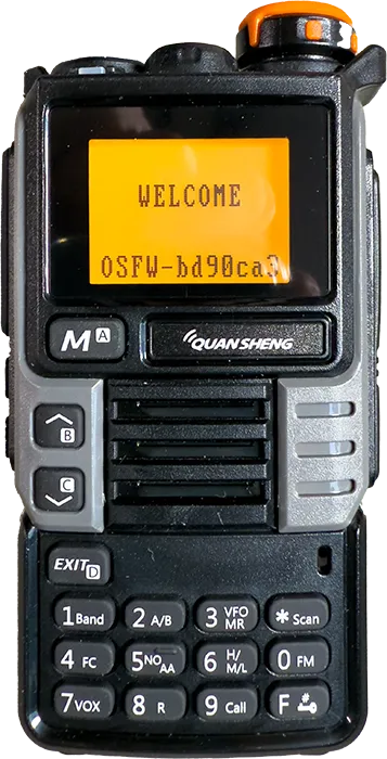
Features:
- VHF UHF dual band standby and 50-600MHz full band receiving
- Frequency meter function
- Cross-band communication
- FM radio/air band receiving
- VOX (voice operated transmission)
- 10 channels America NOAA weather forecast
- Built-in LED light torch
- 200 memory channels
- Wireless frequency copy from other radios
- Wireless radio replication
- DTMF and 1750 tone
- Automatic/manual emergency alert
- 10-group scrambler
- Frequency/DCS/CTCSS scan
- Digital signal CTCC/DCS
- 1600mAh rechargeable li-ion battery pack
- USB TYPE C and desktop cradle charging
Frequency Range:
- F1: 50.0000-76.0000MHz (RX only)
- F2: 108.0000-135.9750MHz (RX only)
- F3: 136.0000-173.9750MHz (TX and RX both)
- F4: 174.0000-349.9750MHz (RX only)
- F5: 350.0000-399.9750MHz (RX only)
- F6: 400.0000-469.9750MHz (TX and RX both)
- F7: 470.0000-600.0000MHz (RX only)
- FM Radio: 76.000-108.000MHz
Technical Parameters:
- Size: 115 x 60 x 37.5mm/4.5 x 2.4 x 1.5"
- Weight: 234g/0.5"
- Working temperature: -20℃ to +60℃
- Antenna impedance: 50Ω
- Modulation mode: FM: 11KOF3E (12.5KHz) and 16K0F3E (25KHz)
- Number of NOAA channels: 10
- Battery capacity: 1600mAh
- Audio power: ≥0.5W
- Audio distortion: ≤10%
- Transmitting power: ≤5W
- Waterproof: IP57
- Maximum Range: 3km-5km
Overview
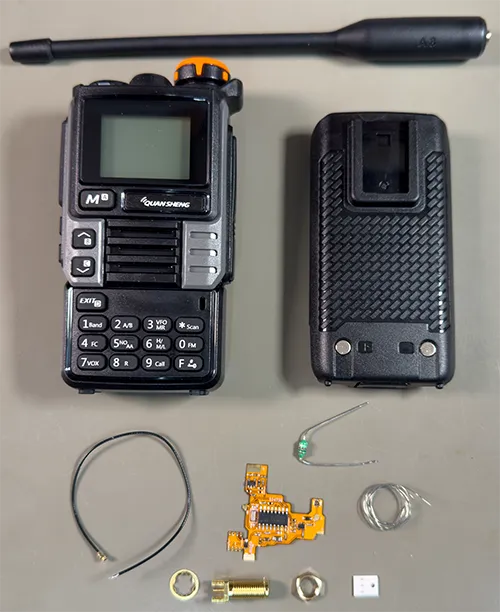
The radio differs from the many other similar models with the ability to flash custom firmware into the radio. This allows different configurations and features to be added to the original and modded hardware.
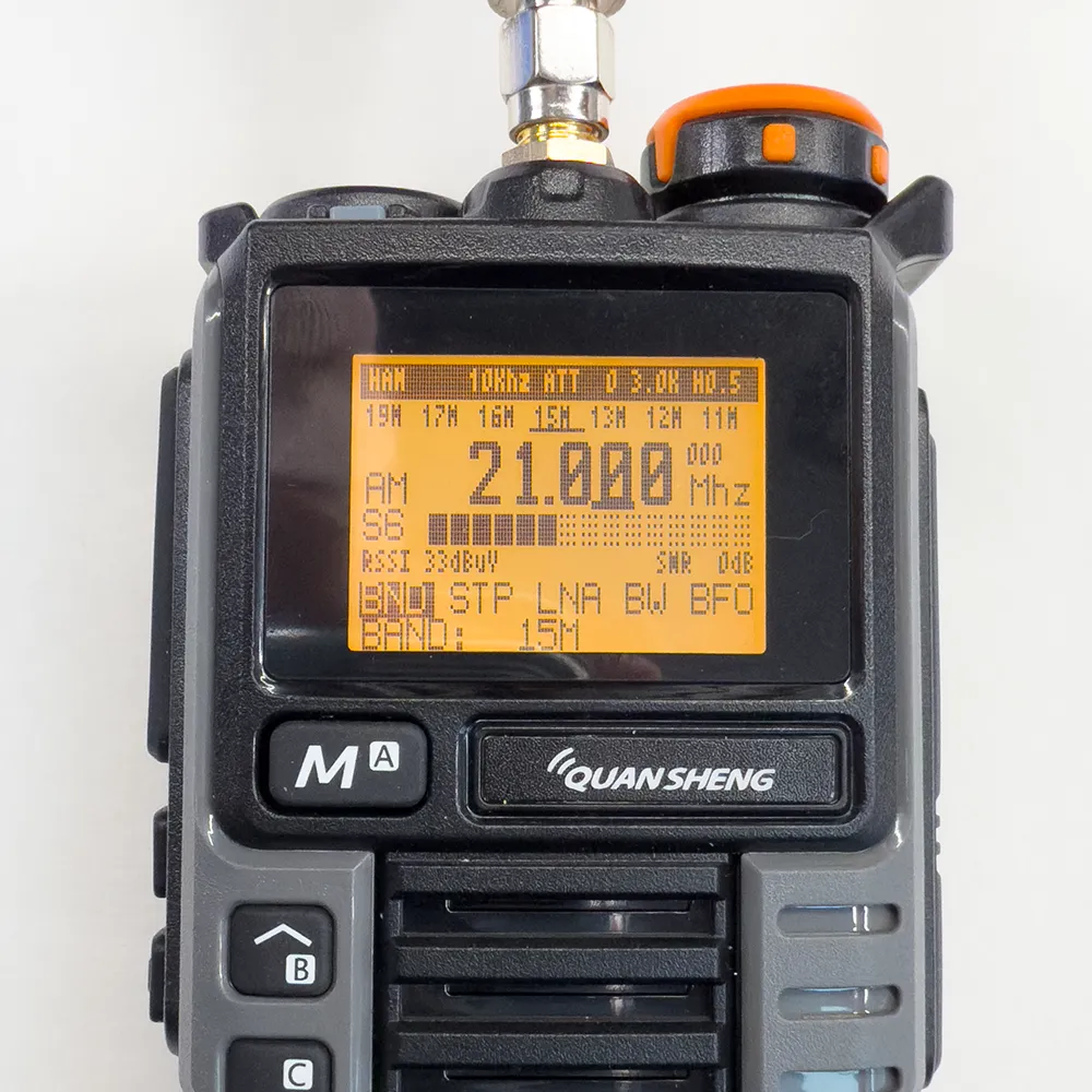
A third party modification board can also be installed to add HF band reception with CW, Upper sideband and Lower sideband modes via a secondary antenna connector fitted to the top of the radio.
This adds the following features:
- Adds an RF amplifier to improve AM reception performance.
- Adds an audio amplifier to solve the problem of extremely low volume of SSB single sideband levels.
- Redesign FM and HF bandpass filters
- SMA antenna port giving a dual-antenna input, with n additional level of band-pass filtering added to the HF antenna input.
Parts Used:
Quansheng UV-K6 Upgrade UV-K5 (99) Interphone 5W Air Band Radio Tyep C Charging UHF VHF DTMF FM Scrambler NOAA Wireless Frequency from AliExpress aliexpress.com/item/1005006702518085.html.
SI4732 Chip And Crystal Oscillator Component Modification Module For Uvk5/K6 PLUS FPC Version For Quansheng UV-K5 UV-K6 from AliExpress aliexpress.com/item/1005007279180829.html.
UVK5CEC firmware from github.com/phdlee/uvk5cec
Programming Software: UV-K5/UV-5R Toolkit Utility for Reading/Writing EEPROM and Flashing Firmware from github.com/qrp73/K5TOOL.
USB Programming Cable for Baofeng UV-5R from Amazon (Affiliate link).
Modifying the radio
There are several video tutorials for modifying the Quansheng radios including youtu.be/UXaLTA0y90c from OM0ET for the version 2.5 board and youtube.com/watch?v=CZBghPwpro4 for the version 3.0 board with Bluetooth.
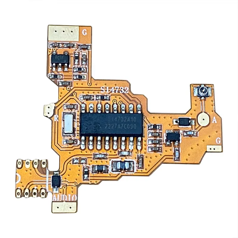
The HF mod is a small flexible PCB which installs into the front of the radios main PCB. The kit we ordered comes with an SMA connector, small coax, thin single strand wire, resistor and capacitors which we did not use.
Installation
1Removing the radio from the case
Unscrew the antenna from the top of the radio and remove the volume control by pulling it off the spindle. Remove the battery and using a thin bladed tool or spudger / pry bar (https://amzn.to/3BTRej3) , gently insert the tool into the bottom of the radio between the plastic case and the metal battery compartment and carefully lift the metal chassis away from the plastic case. This will pull up and away from the top of the radio. Take care as the speaker is mounted into the front of the case using two thin wires.
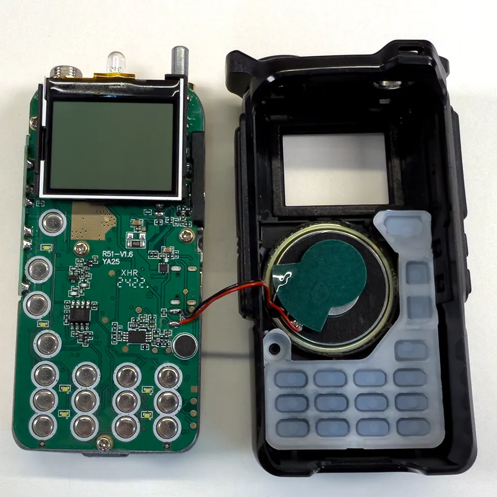
2Unsolder the speaker wires
Using a soldering iron, unsolder the two speaker wires from the PCB.
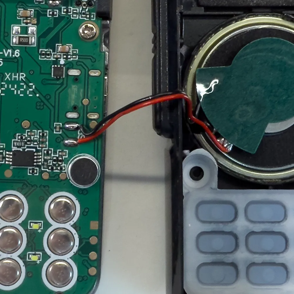
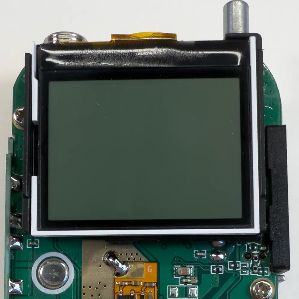
3Unclip the display
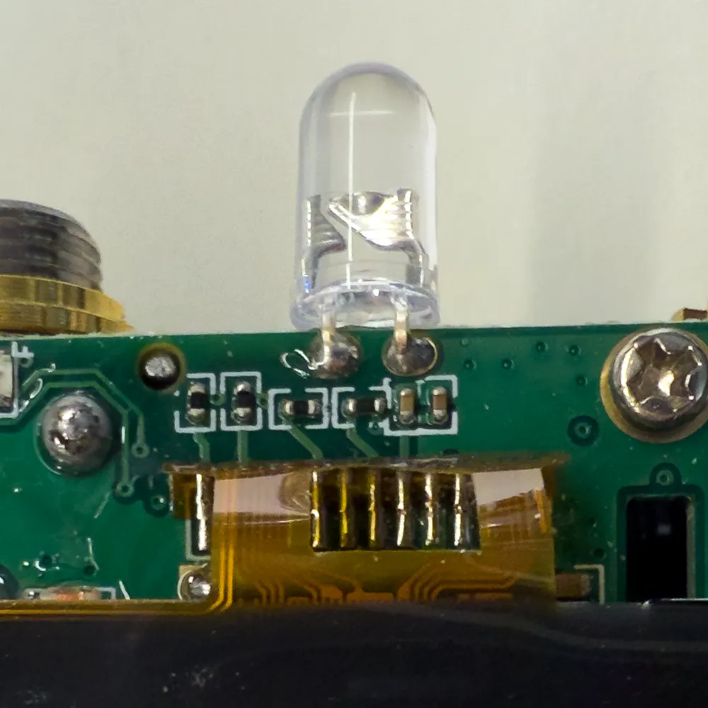
The LCD display enclosure is held in place using small plastic clips to the PCB. Carefully unclip the display taking care not to damage the flat-flex cable. This will give you access to the top LED which needs to be removed.
4Remove the LED
Using a soldering iron, remove the torch LED from the PCB. Hold the display away from the LED pins when unsoldering the pins.
5Reinstall the display
Click the display plastic enclosure back into the PCB.

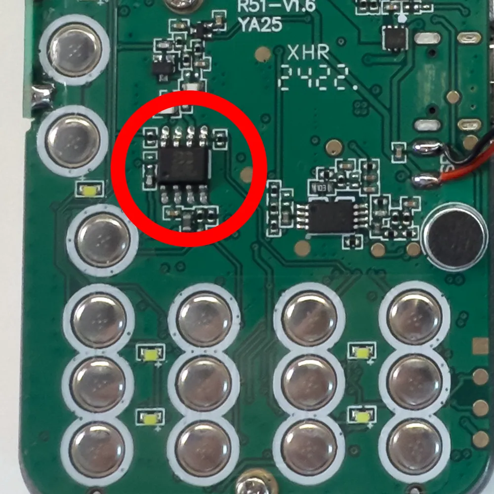
6Remove the FM radio chip
We now need to remove the 8 pin SOIC package radio chip from the PCB. This can be removed with a soldering iron by heating the pins on one side and carefully lifting the side of the chip then heating the other side or by using a hot air gun to remove the chip. If you are using a hot air gun I recommend using a high temperature tape such as Kapton tape to protect the other nearby components.
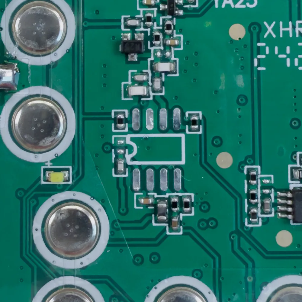
7Clean the solder pads
With the radio chip removed, clean the solder pads using solder wick / braid (https://amzn.to/3W3XcF4) and a soldering iron to remove any remaining traces of solder.
Clean the pads using isopropyl alcohol to remove any traces of solder flux. Also clean the larger ground pane area below the display as the new mod board will be soldered to this point.
8Add double sided tape
We need to add thin double sided adhesive tape to the mod board to hold it in place. Apply the tape to the board and carefully trim to the edges of the PCB. Do not add tape to the part of the board with the 8 solder pin connections as this needs to be soldered to the main PCB using the pads from the removed radio chip.
9Fit the mod PCB
Remove the backing from the double sided adhesive tape and carefully place it onto the pcb aligning the pins from the 8 pin SOIC connections and is placed across the PCB. The top ground connection will overlap the ground pad below the display.
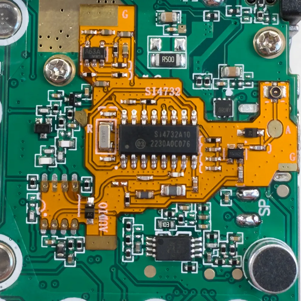
10Soldering the PCB’s
Solder the ground connection and 8 pins for the SOIC chip taking care not to cause any solder bridges. Any excess solder can be removed using the solder wick / braid.
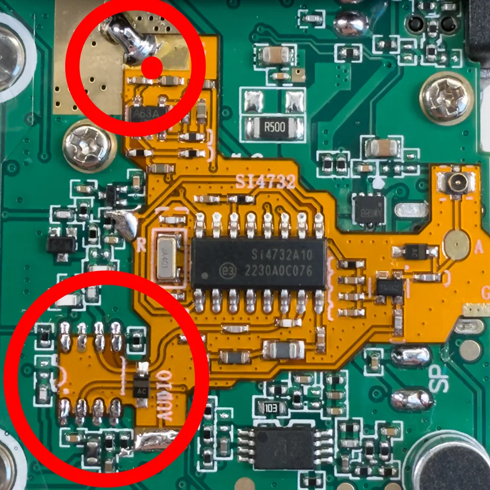
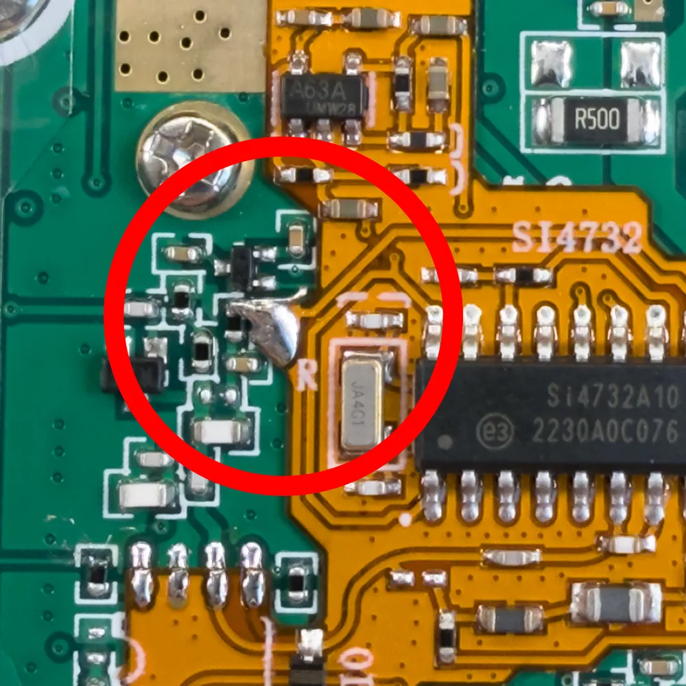
11Solder to resistor
Using the thin wire supplied with the kit, you need to create a link between the top of a resistor as shown in the photo to the pad on the left side of the mod PCB.
12Solder sound output to resistor
Using the thin wire, you need to create a link to the lower side of a resistor as shown in the photo to the pad on the lower edge of the mod PCB.
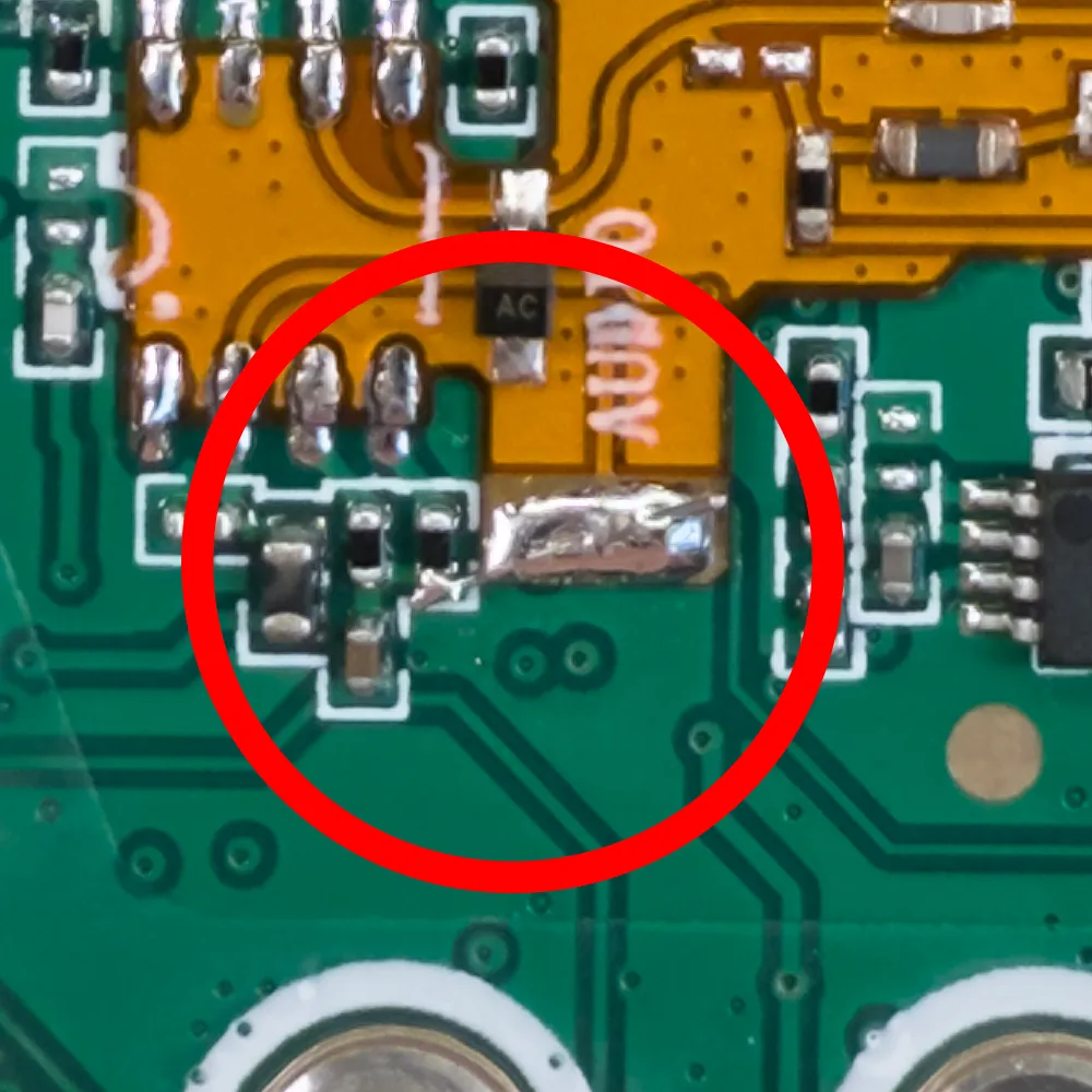
13Clean the PCB
Using the isopropyl alcohol, clean the new solder connections to remove any traces of solder flux.
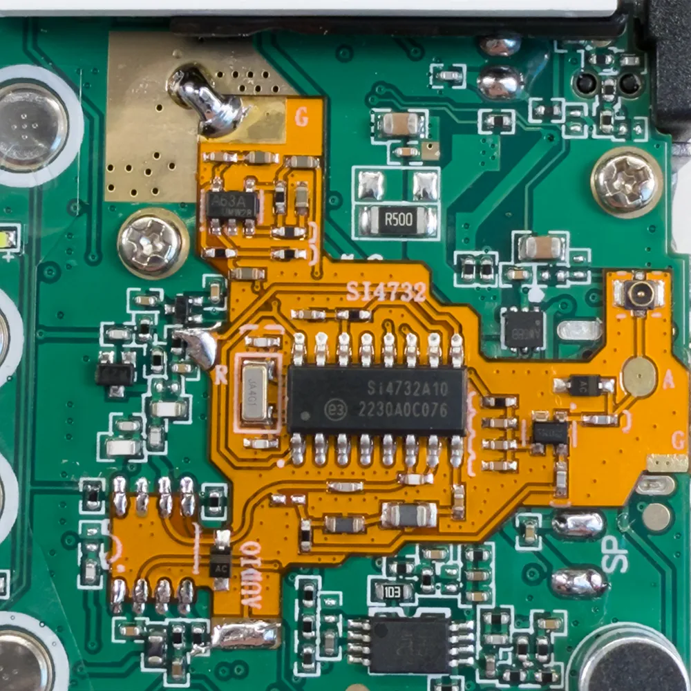
14Update Firmware
Before modifying the case for the new antenna port, it is recommend to update the firmware in the radio to ensure the new mod board is working. See below for firmware update instructions.
15Modify the SMA socket
You will need to remove the small pins on the rear of the SMA socket to allow it to fit flush into the case, these can be removed using a sharp pair of cutters and use a small file to remove any remaining metal. The centre pin will also need to be trimmed to be as close to the plastic insulator as possible.
The new SMA connector will be installed in the top of the case using the hole where the LED was installed.
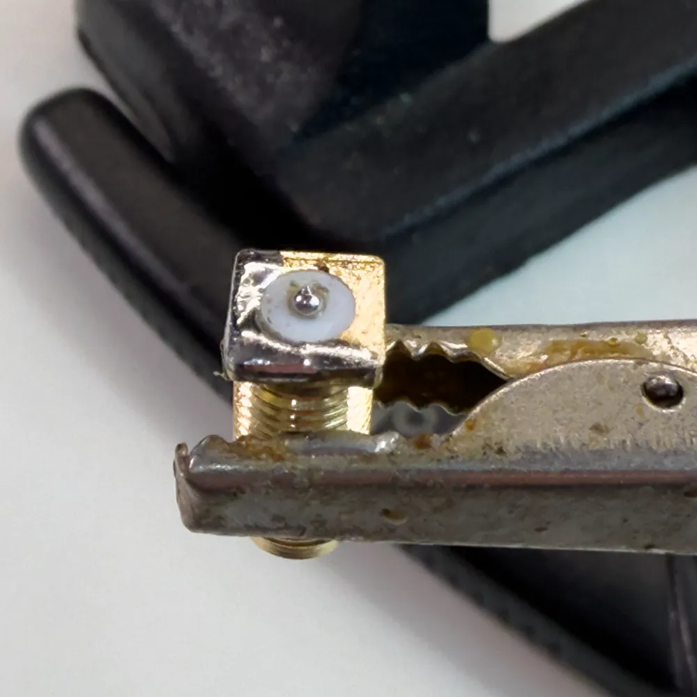
16Solder coax to connector
Using a soldering iron, apply a small amount of solder to the centre of the SMA connector and solder to one corner.
Solder the small coax to the connector so the cable exits the connector to one side.
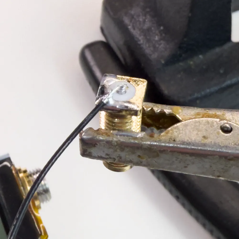
17Fitting the SMA socket connector to the case
You will need a 6.5mm drill and a small rotary grinding tool such as a Dremel Multitool( https://amzn.to/3BHiIsi) and a small milling cutter bit such as the Dremel Milling Cutting Bits set (https://amzn.to/4iWHgxY) to remove plastic from the inside of the case.
Using the 6.5mm drill, carefully drill the LED hole to allow the SMA connector to be installed. Take care not to scratch or damage the screen in the front of the case.
Using the multitool carefully remove plastic from inside the case to allow the square outside edge of the SMA connector to be fitted flush with the inside plastic.
Remove all plastic cuttings from the case.
The SMA socket can now be fitted into the case using the supplied locking washer and nut.
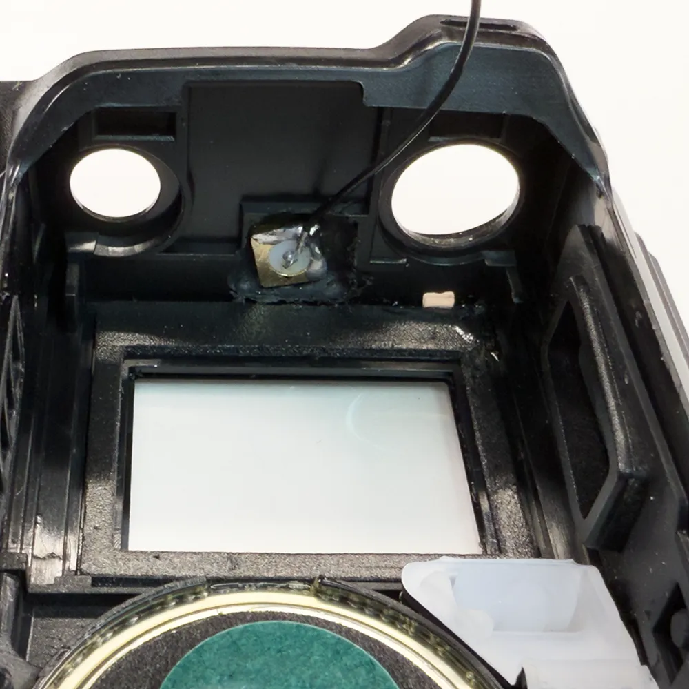
18IPX Coax connector
Next we connect the small IPX connector and coax to the socket on the right side of the PCB. Route the coax along the right side of the display to the top of the radio.
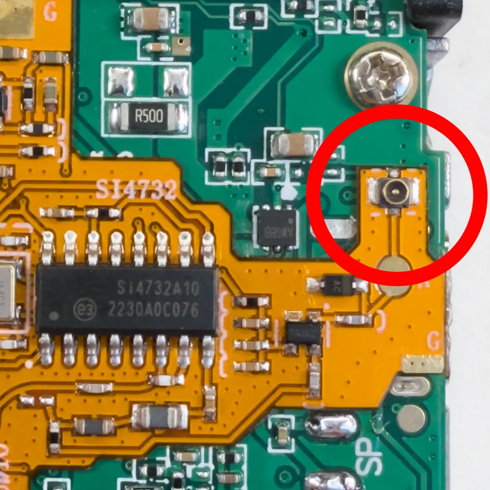
19Reconnect speaker
The two speaker wires can now be soldered back to the main PCB.

20Final assembly
With the speaker and antenna port now connected you can now install the battery to perform a final test before the metal chassis is fitted back into the plastic case.
If everything is working you can now remove the battery and carefully install the metal radio chassis into the case and front panel. Ensure there are not any plastic cuttings or dust on the inside of the case and screen.
Slide the radio connectors and volume control through he holes in the top of the case and ensure the new coax is not blocking the display and being trapped between any components. The radio can now be fully reassembled and is ready for use.
Updating the Firmware
The following instructions used a Windows 11 computer but other programming tools are available for Linux and Mac OS.
We used the UVK5CEC firmware from https://github.com/phdlee/uvk5cec and compiled versions are on the releases page at https://github.com/phdlee/uvk5cec/releases
We downloaded the cec_0.3QB.packed.bin firmware for the radio.
We used the UV-K5/UV-5R Toolkit Utility for Reading/Writing EEPROM and Flashing Firmware from https://github.com/qrp73/K5TOOL to program the radio. Download the latest version from the releases page at https://github.com/qrp73/K5TOOL/releases and unarchive the ZIP file to your computer.
You will have a new folder with the following files:
K5TOOL.exe
k5tool
Copy the firmware file into this folder.
Connect the programming cable to your computer and using the device manager find which COM port the cable is using.
Open a command prompt / terminal and navigate to the folder containing the k5tool and firmware file.
The following commands are based on the programming cable being assigned to COM3, change to the port used on your computer if required.
Test the connection
Connect the programming cable to your radio and power on the radio.
Enter the following command to check the connection to the radio:
k5tool -port COM3 -hello
This should return radio information similar to the following:
Opening COM3
Handshake...
   Firmware:         "2.01.32"
   HasCustomAesKey:  0
   IsPasswordLocked: 0
Done
Writing new Firmware
Use this command arguments to write new firmware to the radio:
-wrflash
Please Note: This command should be executed in flashing mode. To switch to flashing mode, follow these steps:
- Disconnect the cable.
- Turn off the radio.
- Turn the radio back on while holding down the PTT (Push-to-Talk) button.
- Reconnect the cable and then execute the command.
This ensures that the radio is in the correct mode for flashing the firmware image.
To write the new firmware to the radio use the following command:
k5tool -wrflash cec_0.3QB.packed.bin
Replace cec_0.3QB.packed.bin with the name of the firmware you downloaded.
After the firmware has been installed, turn off the radio and disconnect the programming cable. Turn on the radio and the new firmware should be installed and working.

Ben
What is the little green choke (inductor?) used for? It is included in the kit, but I don't see anything in your instructions that address it. In OM0ET's video, he also shows it in the kit, but never installs it. Can you please clarify?
Brian
I think the green part was optional on different models of the radios
kr0m
I think it's only required if you want to use the regular antenna connector without additional antena.
But i'm not sure.
Dan
Any chance you could do a new video for v6.8 board? It's a massive improvement over 2.5 and 5.0. Basically combining all the benefits of 2.5 and further improving how easy the installation is. Would be massively appreciated if you eg. don't mind ripping your old board off, or buying even another UV-K6 for $25. 🙏🙏🙏