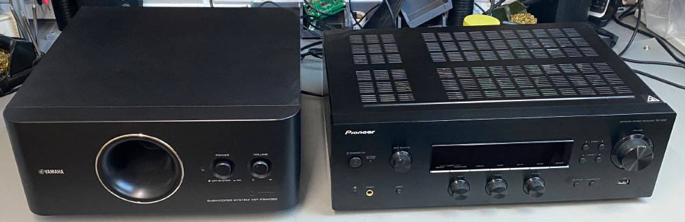
For several months now we have been looking at ways to reduce the energy consumption in our house. One item we found that was using power when it wasn’t in use was a Yamaha subwoofer that is connected to a Pioneer SX-N30 network stereo receiver.
The subwoofer is powered separately from the receiver and we often forget to turn the subwoofer off when it is not in use. A quick measurement with our HOPI meter showed that even when not in use the subwoofer was consuming around 10W of power, so a way was needed to make the subwoofer automatically turn off when the stereo receiver is switched off.
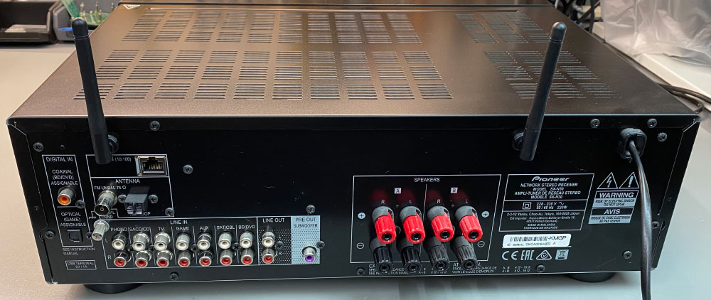
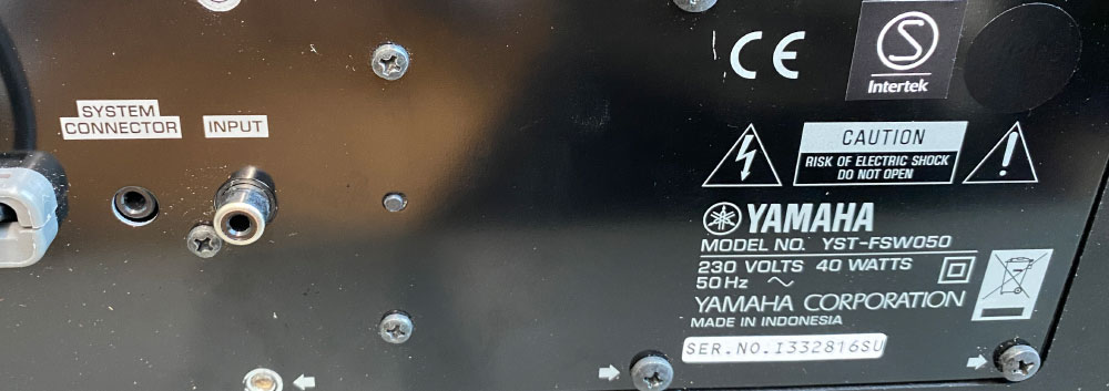
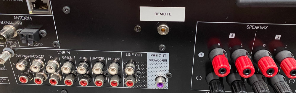
The subwoofer is a Yamaha model YST-FSW050. Inspecting the rear of the subwoofer revealed that it has a system connector which after a search on google was found to be a 12V input designed to switch the subwoofer on remotely. Unfortunately, the Pioneer receiver does not have a 12V output on the back, the next model up does but it was excluded from this model so the only option was to take the receiver apart and find a suitable 12V power source.
Removing the top cover from the receiver revealed several circuit boards and a large transformer. The transformer feeds into two circuit boards.
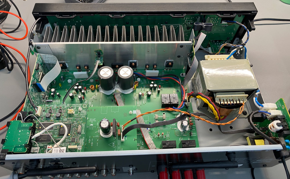
The first and largest board appears to be the amplifier stage. The transformer connection on this board feeds into the amplifier so we didn’t want to connect an extra feed off this section in case it introduced any noise into the amplifier.
The second board was a power regulator for the main control board and a smaller network board that deals with ethernet and Wi-Fi connectivity. A large bridge rectifier and several capacitors rectified and smoothed the AC voltage down to 15V DC and 3.3V DC. This power supply would be a suitable candidate for the 12V output, we just needed to drop the unregulated 15V down to the regulated 12V.
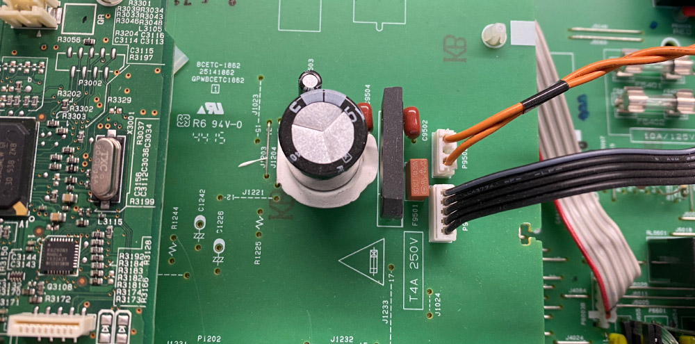
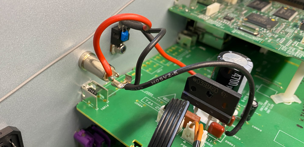
To create a regulated 12V output we used an LM7812 linear regulator with a 100nF capacitor on the output. Two holes were drilled into the rear of the receiver, one to hold a 3.5mm jack socket for the 12V output and a second smaller hole that would be used to secure the LM7812 regulator. The rear panel would act as a heatsink and as a useful spot to mount the regulator next to the 3.5mm jack socket.
Wires were soldered onto the regulator and the output capacitor was fitted directly to the regulator's leads with some heat shrink tubing used to insulate each lead. The input wire was soldered onto a suitable link wire on the power supply PCB. The output wire was soldered to the centre pin on the jack socket and the ground wire was soldered between the bridge rectifiers’ ground wire, the regulator and the chassis ground on the jack socket.
After powering up the receiver we checked the output on the jack socket and found a steady 12V DC. We connected a cable between the jack socket on the receiver and the system connector on the subwoofer and when the receiver was powered up the subwoofer turned on. After turning off the receiver it takes around 10 seconds for the subwoofer to power down as the capacitor in the receiver must discharge.
Hopefully, this simple modification will save a little bit on our energy bills and we no longer need to remember to switch off the subwoofer when it isn’t being used.
The video below shows the sub turned on via the remote power output on the main amp.
Thomas
Hello. I have the same amplifier model and I am also thinking about similar modifications. Some notes on your solution: Safety first. Have you considered what can happen in the event of an output short circuit? I think it would be advisable to include a short-circuit current limiting resistor in series. Second: Note that the SX-N30 ELITE model has a trigger output. It is located on the board from which you took 12V. In your photos you can see the place where the appropriate sockets should be soldered. Maybe it would be worthwhile to fill in a few missing elements and get the "factory" trigger output. Best regards. Thomas
Turkel
Hello, I came across the web search to your blog. I also have same amplifier (Elite version), but I have problem with voltage rating. It is 120V but I want to use it in EU with 220V mains. Do you think Transformer have also 220V input or it is only 120V transformer ? Fuses inside are 125V so are they only limit to use item with 220V mains or some more modification need to be done on Transformer or on initial power switch PCB?
Regards,
Turkel.
Brian
Hello Turkel
There maybe a voltage selection switch near the transformer inside the case or rear panel to switch between 220 and 120 volts otherwise you can buy step down transformers to bring the EU 220V down to 120V for the amp.