We recently purchased a Maynuo M9812 programmable DC electronic load to use on various projects and one of the features of the M9812 is a serial connector that can be used to connect the load to a pc for external control and data logging. Maynuo sells a USB adapter cable but they cost around £40 and are fairly bulky for what is basically a USB to serial adapter, so we decided to try and make our own cable.
The Maynuo M9812 manual includes a description of the DB9 serial interface. Only four pins are connected, pin 1 is +5V, pin 2 is TXD, pin 3 is RXD and pin 5 is ground. The interface uses 5V TTL level signals so a standard USB to RS232 serial adapter would not work as the voltage levels and pinouts would be incompatible. Another aspect that needed consideration was the ground on the M9812 is connected to the ground pin on the front input connector, this would mean that if you used a standard interface cable you would create a common ground between the M9812 and the PC which could cause problems when making measurements. To get around the common ground problem the USB and UART connectors would need to be galvanically isolated.
After looking at the various ways we could design an interface cable we decided to use an FTDI FT230X USB to UART chip in an SSOP package for the USB side of things and an ISO7421 digital isolator from Texas Instruments. We have used the FT230X on other projects in the past and it is easy to work with plus it has good driver support for Windows and Linux. The ISO7421 is an 8-pin SOIC package that provides up to 2.5KVrms voltage isolation and is compatible with 3.3V and 5V logic which is useful as the FT230X works at 3.3V and the M9812 uses 5V.
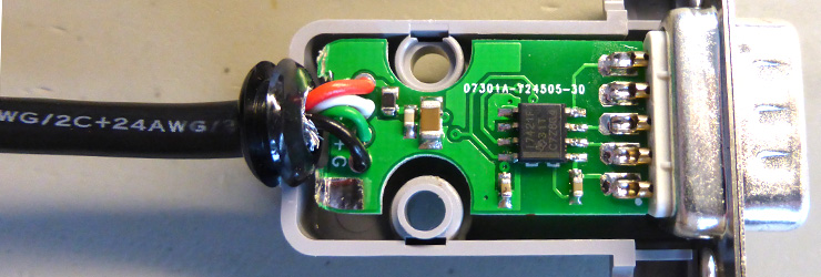
We followed the schematic guidelines in the FT230X datasheet for the USB connection with 24R current limiting resistors and 47pF capacitors on the USB D+ and D- lines and a ferrite bead, 100nF and 4.7uF capacitors on the USB 5V line to reduce noise. The FT230X includes an internal 3.3V voltage regulator which was used to supply the voltage to one side of the ISO7421 while the Maynuo M9812 provided the 5V for the other side of the isolator. Two LEDs were included in the design so we could see if the circuit was communicating, although the LEDs are not visible with the cover fitted.
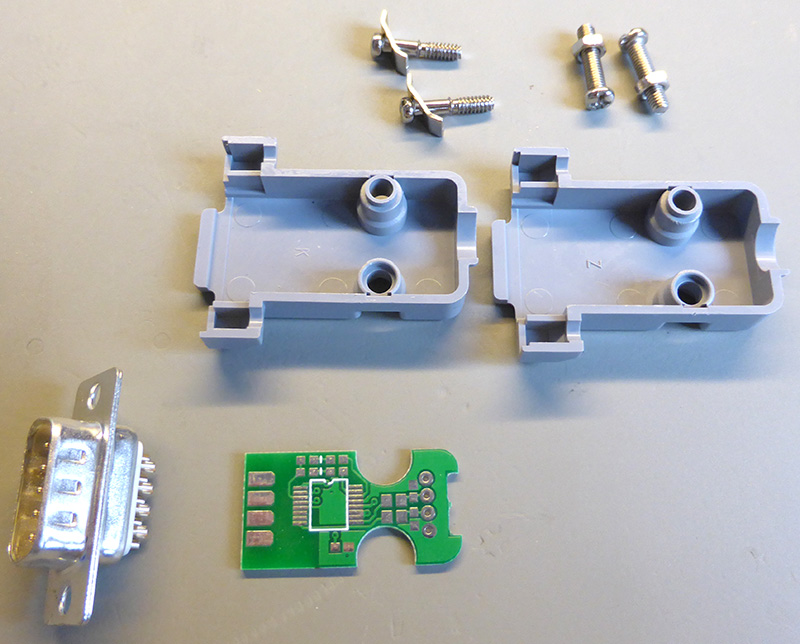
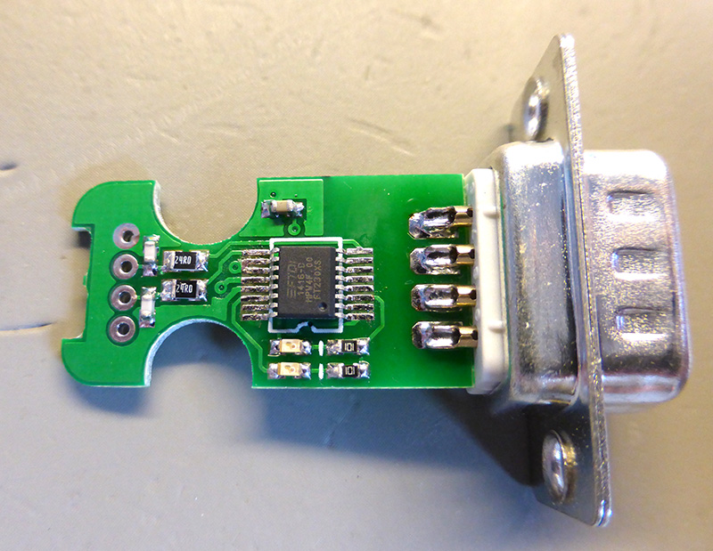
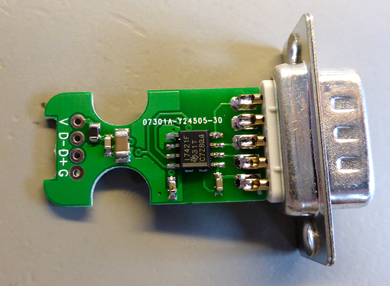
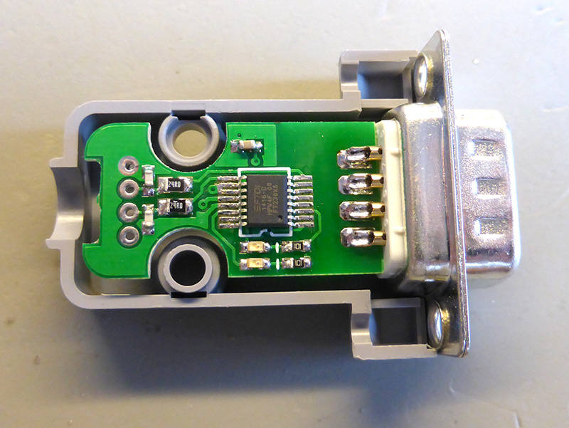
In order to make the interface cable as compact as possible we designed the PCB to fit inside of a DB9 enclosure. This gave us a working area of around 28mm x 15mm with cut-outs for the mounting bolts and a cable strain grommet. The PCB solders directly onto the back of the DB9 connector with components soldered on both sides of the board. Most of the capacitors and resistors are 0603 sizes to save space. The isolation gap between the two grounds is not as wide as I would have liked but it should provide good isolation for the voltages that the electronic load will be used for.
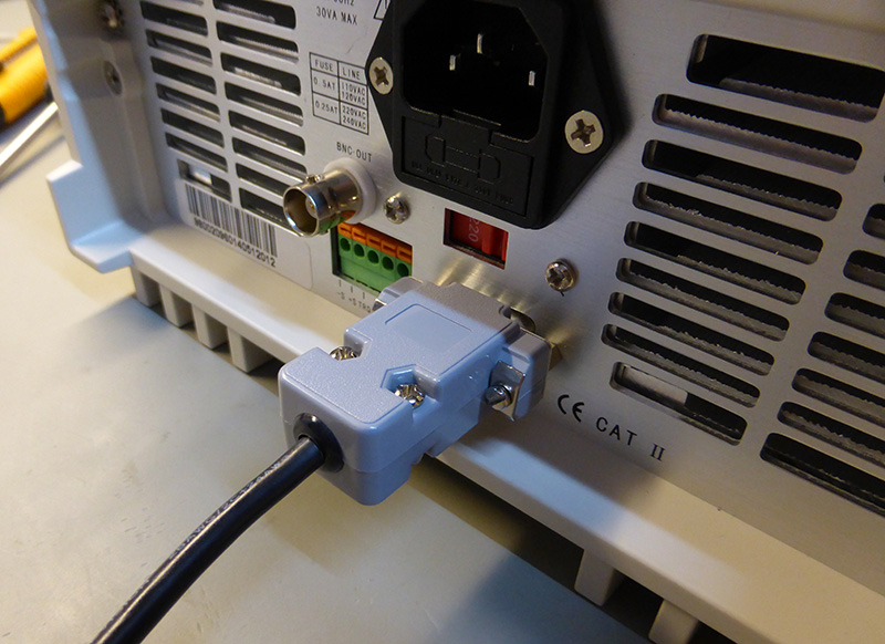
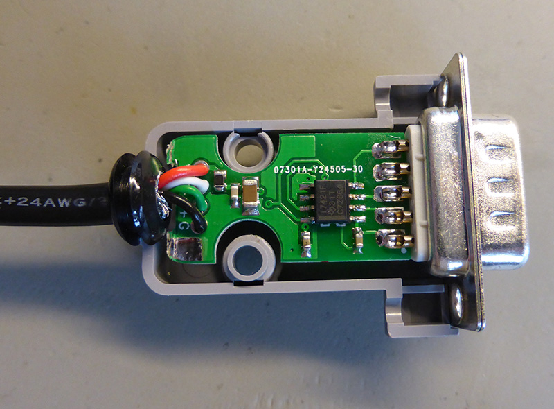
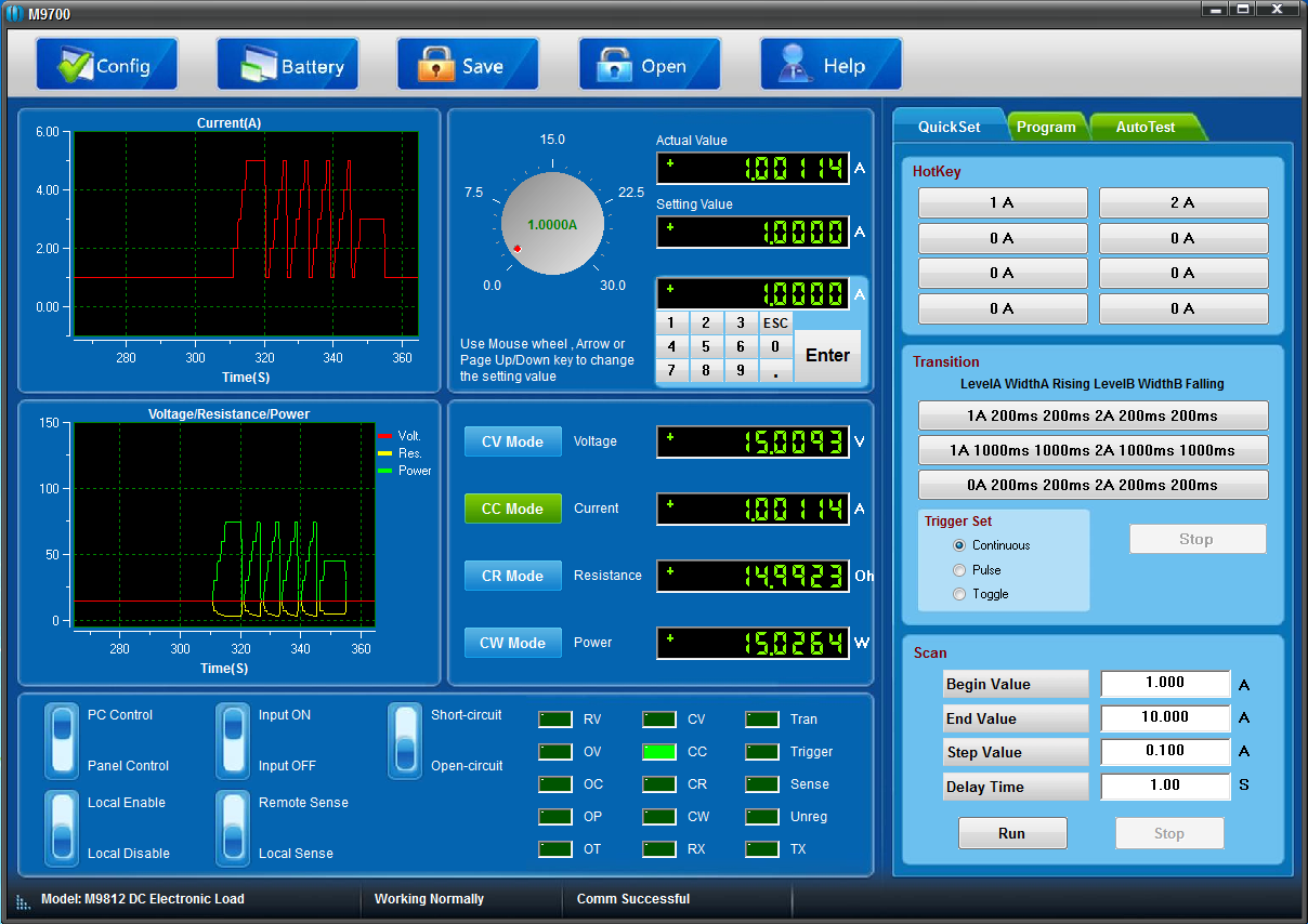
After soldering all of the components onto the board and finding a donor USB cable to go on the end we plugged the cable into a PC and waited for the drivers to install themselves. The board was detected properly and showed up as COM12 in the device manager. We then connected the other end of the cable to the Maynuo M9812, turned it on and fired up their control application. The application detected the Maynuo M9812 and gave us remote access to the device. So far it all seems to be working perfectly.
Download the PCB files in Diptrace format. You can download the free version of Diptrace from https://diptrace.com/
Chris
Hi, Nice work! would you be so kind as to share the drawing for the PBC itself? I am looking to make something for another application and that would save me a ton of time.
thanks!
Brian
Chris, I have added a link above to the PCB files in Diptrace format.
Jan Sundvall
Hi there, great work, thanks a lot for sharing.
Do you know, are USB drivers available for Win 10 for the a FTDI FT230X USB chip?
Have you got it working for Win-10 64 bit?
Cheers Jan
Brian
Hi Jan
There are drivers for Windows 10 which work on x64 and x32 version and you can download them from https://www.ftdichip.com/FTDrivers.htm
J.Fisher
Hey guys,
i was lazy enough and just bought an FTDI cable: https://amzn.to/2Vi7xwP
Now my problem is, with installed driver the Maynuo Software recoginzes my device but i cannot control it.. It shows TX and RX blinking green. Do you have any clues?
Thanks in advance