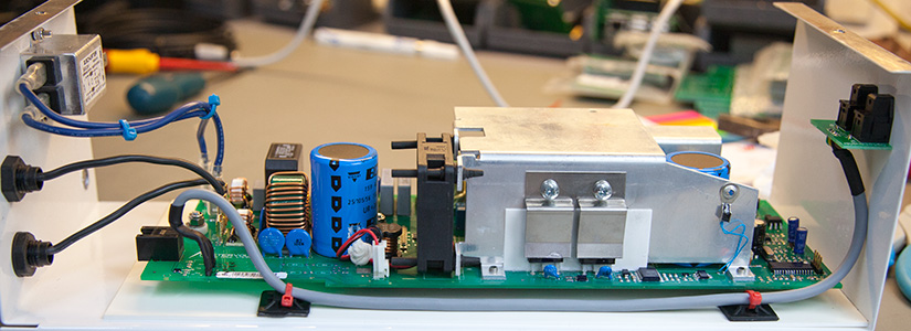
Since we solved the RF interference problems www.briandorey.com/post/mastervolt-soladin-rf-filtering with our Mastervolt Soladin 600 mains inverter we had planned to use the data port to link to our Raspberry Pi based home data logger system so we could record the power generated by the solar PV panels and the inverter.
Due to all the problems we had with the RF interference in the past with this mains grid-tie inverter we didn’t want to use copper wires to connect the built-in UART port to the Raspberry Pi.
In the past, we have used optical Toslink cables and interfaces to connect between isolated systems to enable serial communications and after testing the interface with a UART cable adapter to an Arduino Uno using code from GitHub (repo no longer active) we decided to use the same Toslink cables and interfaces to link the mains inverter to the Raspberry Pi using an Atmel IC to process the serial communications and use the IC as an I2C host which the Raspberry Pi can communicate with to retrieve the data as needed.
When we initially tested the communications with the inverters data port using a long cable we had a few problems with RF pulses being mixed with the serial data which resulted in some corrupt data being returned. We thought that removing the copper wire which was acting as a large antenna would solve the data being corrupted by the RF noise generated by the inverter.
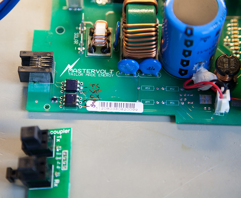
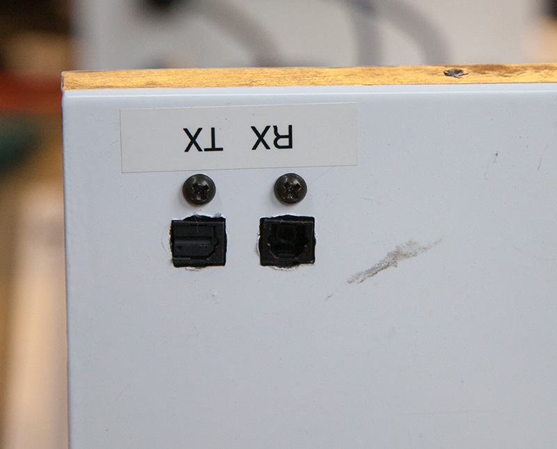
Andrew designed a small PCB which has the RX and TX optical interfaces and also designed a circuit with an Atmel IC to fit on the Raspberry Pi to act as the I2C slave device and optical interface.
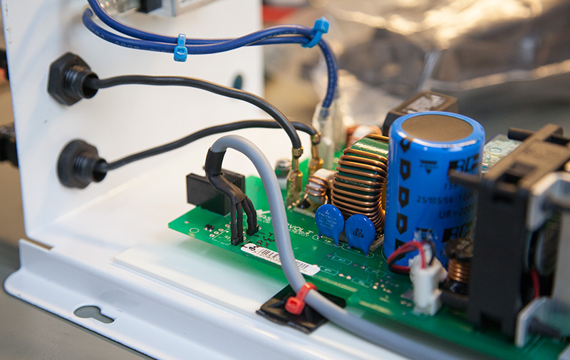
We initially removed the existing Opto couplers from the PCB as we intended to drive the optical interfaces direct from the Microchip Pic on the inverter but this didn’t work on the TX side of the circuit. We then refitted the Opto couplers and drove the optical interfaces from the isolated side of the circuit and found a suitable 5V supply to run the new optical board. We used a screened cable to connect between the PCB and our new optical interface board.
Using our Saleae Logic 8 interface we monitored the TX and RX lines on the Raspberry Pi interface and also on the inverter's new optical board and we found that the data from the Raspberry Pi to the inverter was being received ok and without any noise on the signal but the returned data is sent from the inverter had very bad interference and this was causing the same corrupted data issues we experienced when using the copper wire connection.
We tried connecting the TX pin on the inverter’s microprocessor to the Saleae Logic 8 interface and found the same noisy signal which was being received at the Raspberry Pi was present at the sending end!
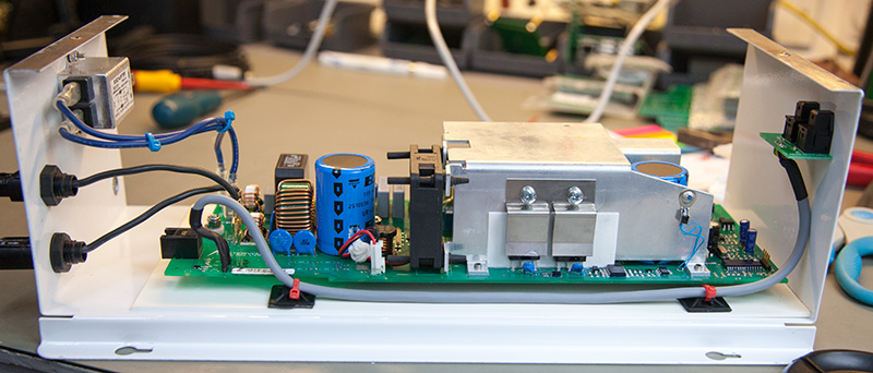
The data PCB traces run the full length of the inverters circuit board and the only way that we can think that the signal is being corrupted is by the length of the tracks being on a resonant harmonic of one or more of the spurious signals being generated by the mains inverting stages on the board.
One possible solution would be to carefully unsolder the TX and RX pins on the microprocessor and lift them away from the PCB and connect these directly to the new interface board but we are reluctant to do this in case we break something!
If anyone has any ideas for resolving these interference problems, please send me an email or leave a comment below.
Comments