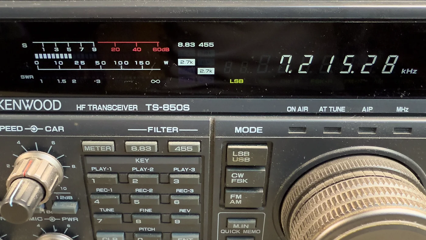
I was recently asked to take a look at a faulty Kenwood TS-850S HF transceiver. Upon powering it on, the unit appeared to function normally with audio output, frequency tuning, and all other core operations were intact, but the display remained completely blank. This is a common issue with these radios and often points to problems with the display backlight.
The Kenwood TS-850S is a desktop HF HAM Radio Transmitter released in the early 1990s and was a popular choice among radio amateurs for both its performance and durability. It covers between 0.1 and 30 MHz and has the following modes: AM, FM, SSB, CW, and FSK. The radio is very solidly built and weighs 9.4 Kg (20.7 lb).
Initial Inspection and Disassembly
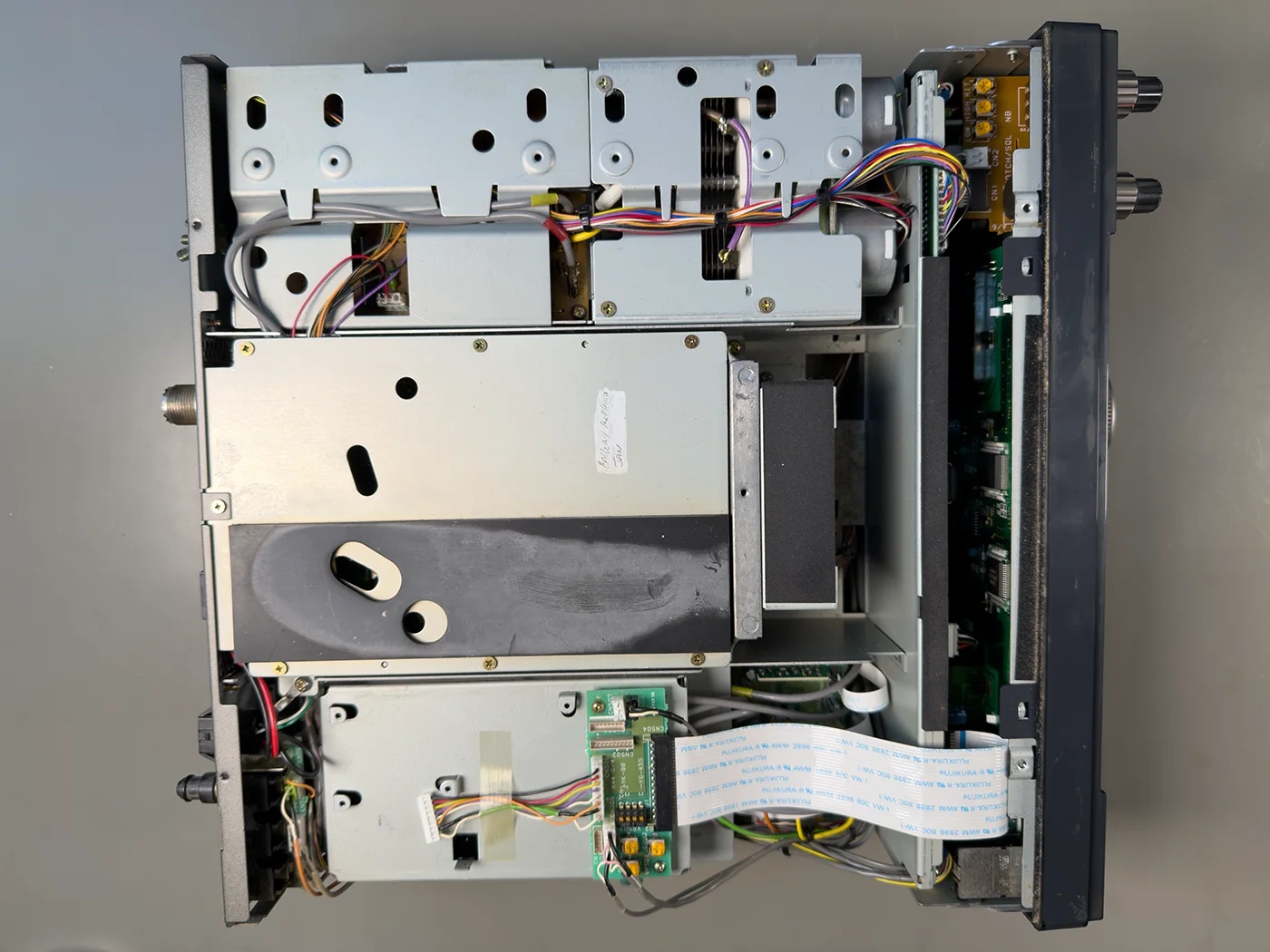
To gain access to the internal components, the upper and lower covers must first be removed. This involves unscrewing 16 screws and disconnecting the speaker connector attached to the upper cover. Once both covers are off, the front panel can be carefully detached by removing four screws located internally.
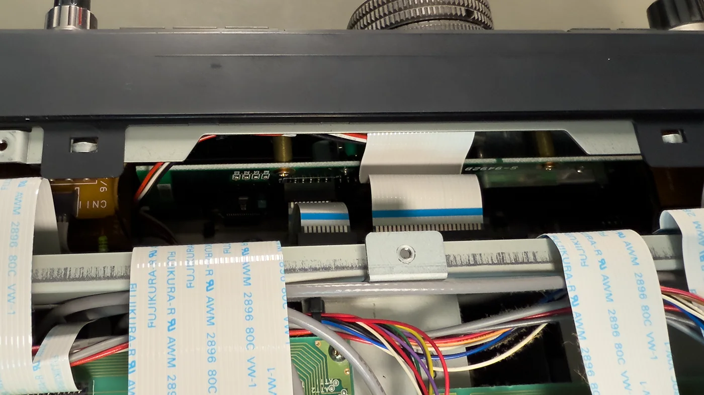
Tip: When folding the front panel down, it’s essential to place a spacer or small block under the front of the radio. This raises the unit off the work surface and prevents putting stress on the front panel controls and ribbon cables, reducing the risk of damage.
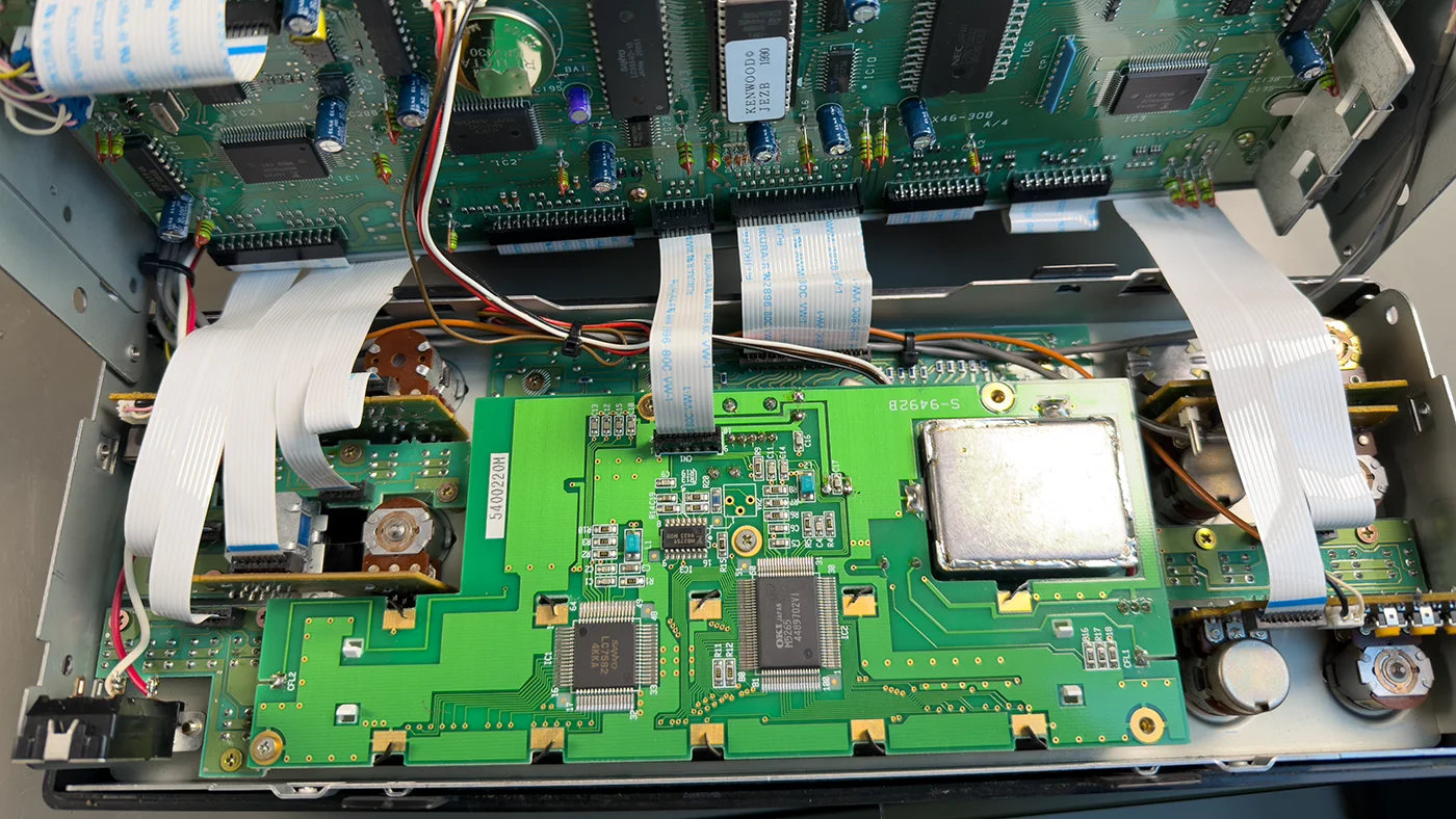
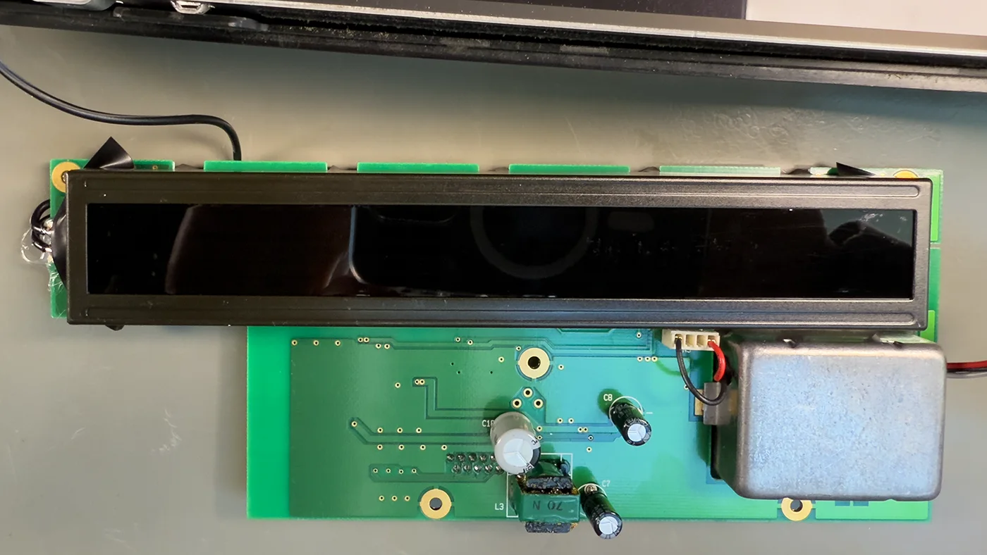
With the front panel safely accessible, the display circuit board can be removed. This involves disconnecting a small flat flex cable and undoing five small screws that secure the board to the housing.
Diagnosing the Fault
Upon initial inspection of the display PCB, one of the electrolytic capacitors was found to be visibly damaged. It had overheated and leaked, which can sometimes lead to circuit failure. We replaced this capacitor, as well as two others in the immediate area as a precaution. Unfortunately, this did not resolve the issue—the display remained unlit.
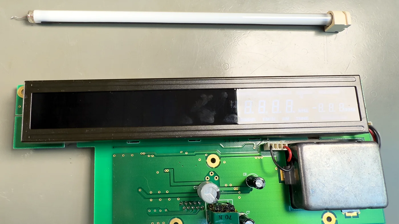
Our next step was to inspect the backlight system. The original backlighting in the TS-850S consists of a compact fluorescent lamp (CFL) powered by a sealed inverter module, which steps up the voltage required to power the tube.
Testing revealed that the CFL was not receiving power, indicating a fault in the inverter module. Since the inverter is a sealed unit and replacement parts are scarce, we opted for a modern and more reliable solution: retrofitting the display with a 12V LED strip salvaged from a previous project.
LED Strip Backlight Retrofit
To install the LED strip, we first desoldered the wires connecting the fluorescent tube to the display PCB and removed the tube itself from the enclosure. The self-adhesive LED strip was then cut to the appropriate length to fit neatly within the rear of the display housing. It was slid into the gap behind the LED and stuck firmly in place.
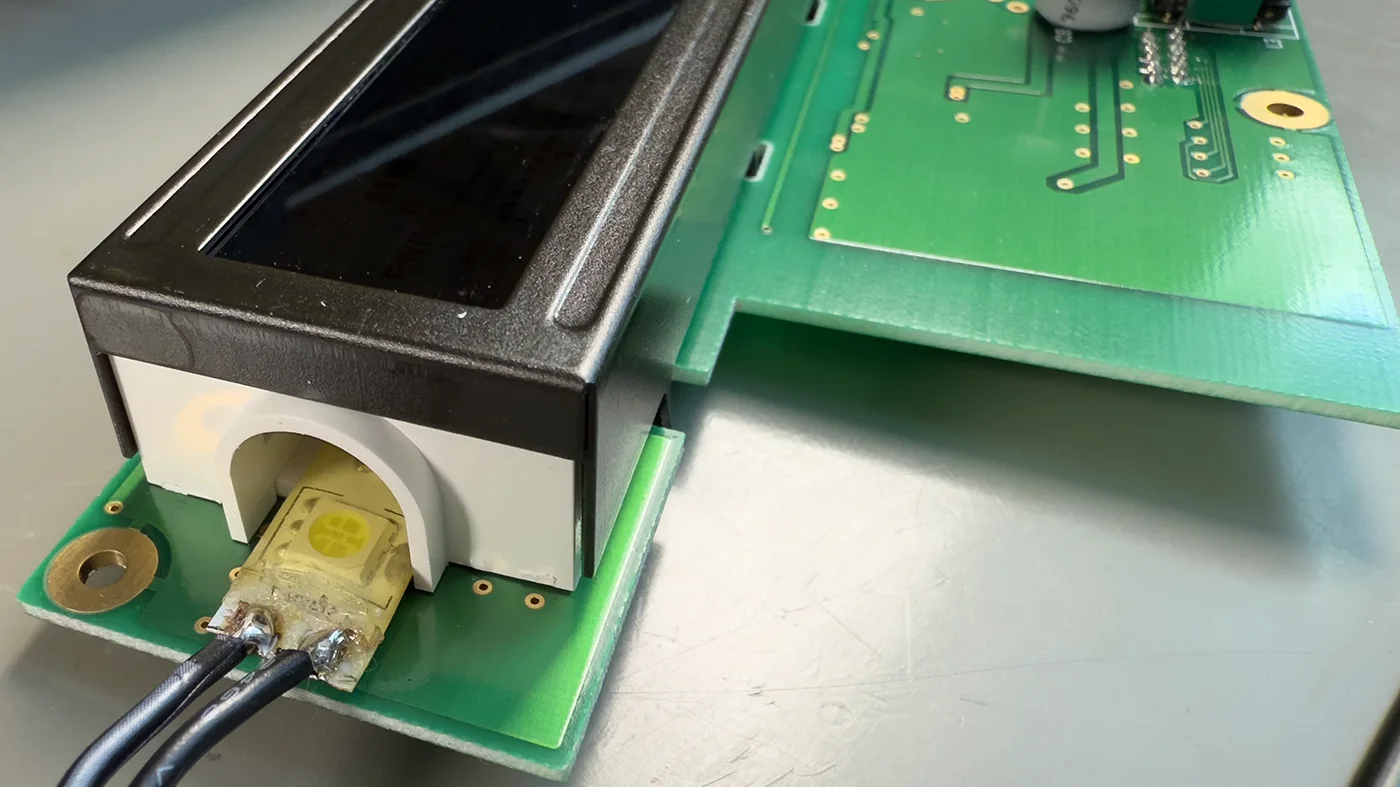
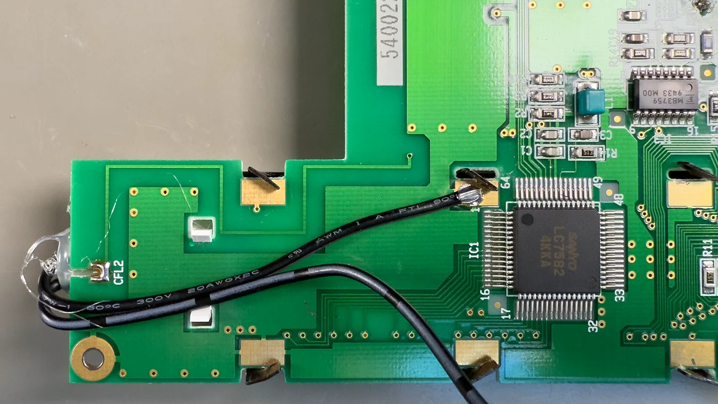
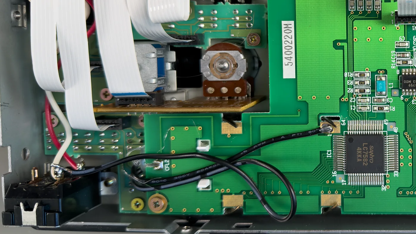
To power the LEDs, we soldered a short length of twin-core wire to one end of the strip. The ground wire was connected to a suitable ground point on the PCB, and the positive wire was connected to the 12V switched line from the radio’s main power switch, specifically tapping into the white wire responsible for switched 12V output.
To prevent movement of the strip during handling or vibration, we secured each end using hot melt glue. Additionally, we applied a small piece of black insulation tape at both ends of the strip to prevent light leakage from the enclosure.
Tidying Up and Preventative Measures
To avoid potential future issues or interference from the now-defunct CFL inverter module, we removed the three-pin connector from the PCB that had supplied power to the inverter. The exposed PCB pins were covered with insulation tape to prevent any accidental short circuits during reassembly.
Reassembly and Testing
With the new LED backlight in place and wiring secured, we reassembled the radio in reverse order reattaching the display PCB, closing the front panel, and reinstalling the upper and lower covers. The radio was powered on for final testing, and the display lit up perfectly with a bright, even glow.
The original display dimmer control no longer functions with the LED strip, as it was designed to control the CFL inverter. However, if dimming functionality is desired, it would be straightforward to integrate a PWM dimmer circuit into the LED wiring.
This backlight failure is a well-known issue with the Kenwood TS-850S, primarily due to ageing inverter modules and fluorescent tubes. The LED strip retrofit provides a clean, cost-effective, and reliable solution that restores full display functionality and breathes new life into these excellent radios.
For anyone experiencing similar symptoms, a working transceiver with a blank display, this repair may well be the answer, and it ensures many more years of reliable operation from the TS-850S.

Epi
Agradezco de antemano la solución dada para resolver el problema del display del TS-850-S de Kenwood entre otras posibles causas, por agotamiento del tubo florescente que alimenta la pantalla. Pero observo que la solucion queda un poco escasa, pues eliminas el DIM (intensidad luminica) y no estabilizas la tension que sería posible a través del integrado 7812.
Espero que en el próximo episodio, lo tengas en cuenta.
73, Cordiales
From Google Translate
I appreciate the solution provided for the Kenwood TS-850-S display problem, which, among other possible causes, is due to the fluorescent tube burning out. However, I find the solution somewhat inadequate, as it eliminates the DIM (brightness control) and doesn't stabilize the voltage, which could be achieved using the 7812 IC. I hope you'll take this into account in the next episode.
Steve
Do you know the exact dimensions of the original CFL tube?
Thanks for any response es 73.
Brian
I am sorry but I dont know the size of the tube.