Disclaimer, this project involves the modification of mains electric-powered equipment and can cause electrocution, shock, death, and fire if not done correctly. I take no responsibility if anyone follows these instructions and causes any damage or worse.
An ongoing theme among many of my projects has been energy monitoring, logging and reduction. To monitor the mains' electric usage for the house we have a custom-made energy logger which uses a mixture of pulse counting and a current sensing coil to capture the mains' usage for the entire house.
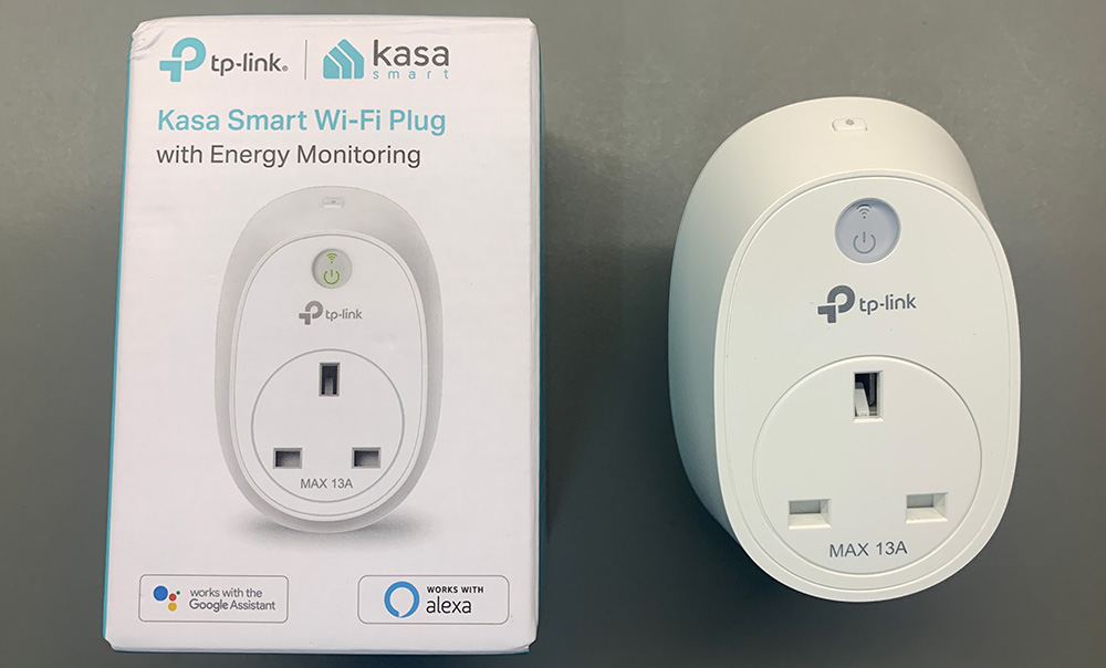
I wanted to be able to monitor individual electrical items and after looking at different commercial products, I decided to order a Kasa Smart Plug by TP-Link model HS10 which has energy monitoring and switching control for the mains-powered device.
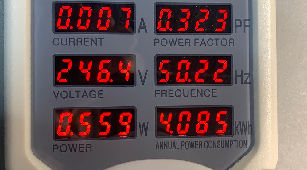
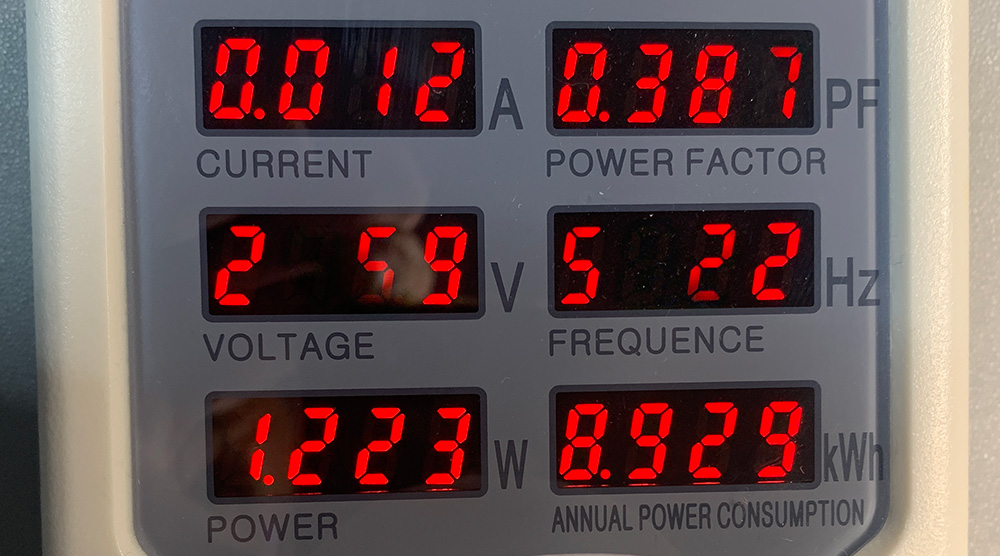
I measured the power consumption of the smart plug using my Hopi power meter and found that it uses around 0.56 watts (4.085 kWh per year) when in an idle state and 1.22 watts (8.93 kWh per year) with the relay turned on.
As I do not need the remote switching capabilities, I decided to try to remove the relay and bypass it internally so the smart plug would just act as an energy monitor.
Accessing the relay and circuit board inside the case involves removing a single screw which is hidden under a sticker below the plug’s pins.
Next, the case is separated using a small screwdriver or thin blade to separate the eight plastic clips around the edge of the case.
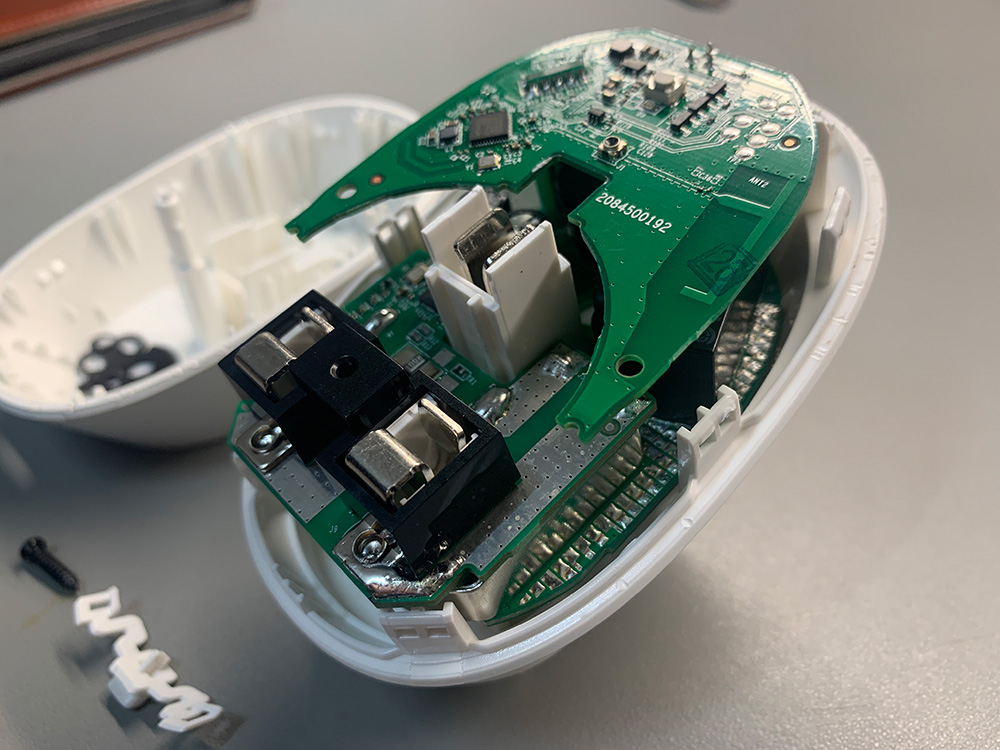
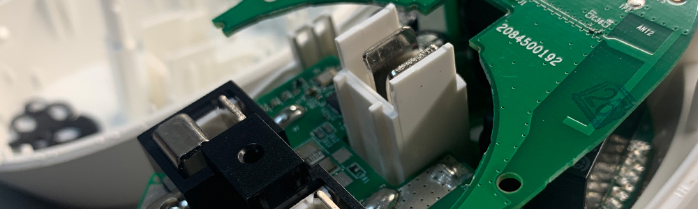
The smart plug has three small circuit boards, the top contains the switches, LEDs and a Wi-Fi module with a PCB antenna, the middle board has the mains electric connections and energy monitoring chips and the lower base board has the power control relay and driver.
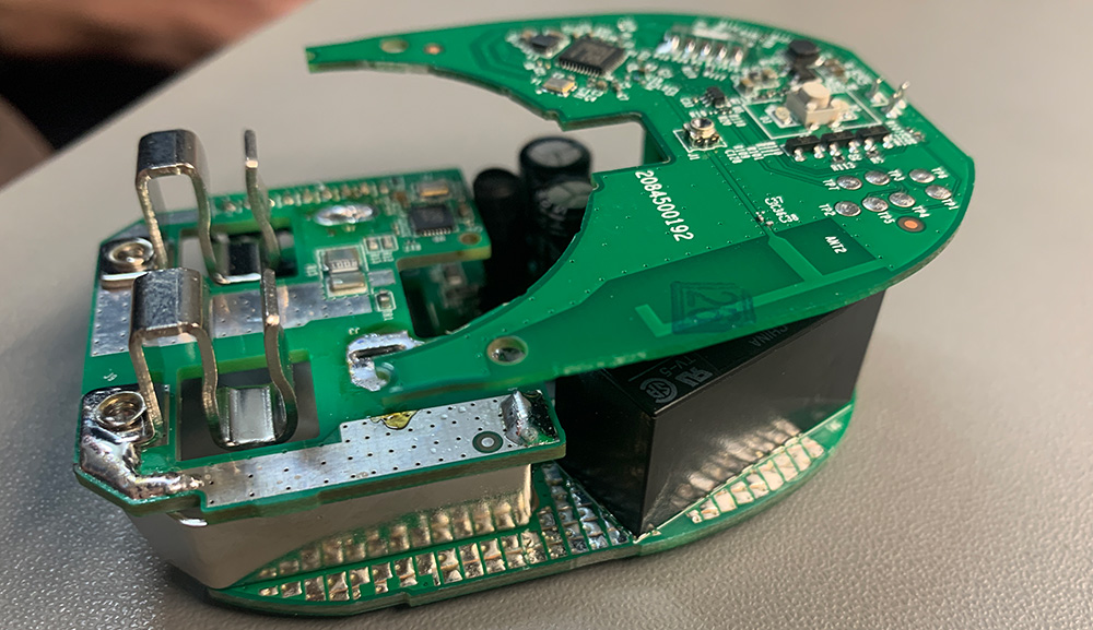
The circuit boards are held into the case via two metal pins from the live and neutral plug pins which are soldered into the central PCB. We tried to remove the solder using my desoldering iron, but it could not generate enough heat to melt the solder due to the large metal area on the board and the plug pins. Next, we mounted the plug into a vice and with two soldering irons, we heated both pins at the same time, using a screwdriver to lift the circuit boards away from the pins.
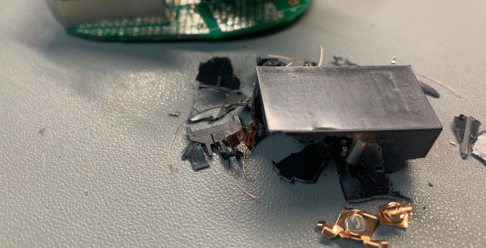
The lower PCB is double-sided to handle the mains current and this made removing the solder on the relay pins more difficult. We had to break the relay apart with cutters to remove it from the board.
Once the relay was removed, the contact pins were bypassed with a short piece of 2.5mm copper wire and then tested again on the Hopi meter.
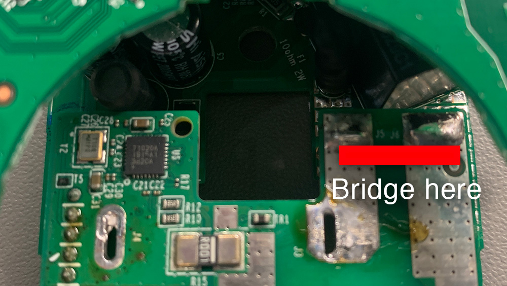
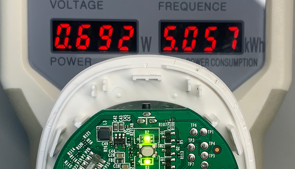
With the plug in its powered-on mode, the current consumption was now 0.69 watts (5.05 kWh per year) so the relay must have been using approximately 0.5 watts to keep it energised.
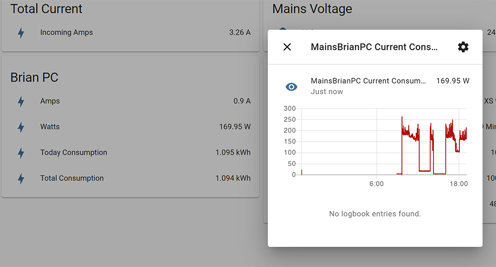
The plug has now been set up on Home Assistant and is being used to currently log the power consumption of my main workstation PC. I will also try it on other devices in the house.
One way to reduce the power consumption further would be to replace the PCB with the Wi-Fi module with one using a ZigBee module as ZigBee is more energy efficient than Wi-Fi but for now that will be left as a future project.
Andru
Pretty neat! Did you have a chance to evaluate the plug accuracy? Is it true rms?
Brian
I tested the plug against a known load and it seems to be close on the current consumption.
Electronic Contract
The Kasa Smart Plug by TP-Link is a game-changer when it comes to power consumption modification. Its innovative design and features make it an ideal choice for those looking to reduce energy usage without compromising convenience. With its user-friendly app, I can effortlessly monitor and control my devices, ensuring they are only powered when needed. The power consumption modification feature has helped me make significant energy savings, resulting in reduced electricity bills and a more eco-friendly lifestyle. Its compatibility with voice assistants and seamless integration with other smart devices make it a must-have for anyone seeking an efficient and sustainable home automation solution. Highly recommended!