DIY CNC Mill Controller for Stepper Motor Milling Machine
This add-on to our CNC mill was made to allow manual control of the mill CNC stepper motors using a pair of 2 axis joysticks obtained from a broken radio control plane radio transmitter.
The circuit uses a 12-series PIC processor to sample the joystick position and determine a centre point. This then sends one output to the mills motor controller for the direction which switches between 0V and 5V via an optical isolator and the second output from the PIC Processor gives a voltage which corresponds to the position of the joystick between 0-5V which goes into a voltage to frequency chip which sends a pulsed output to the mills motor controller for the speed. This is also isolated using an optical isolator to protect this new circuit when the PC is controlling the mill.
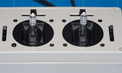
The finished hand controller with the 2 joysticks which came from an old RC plane controller.
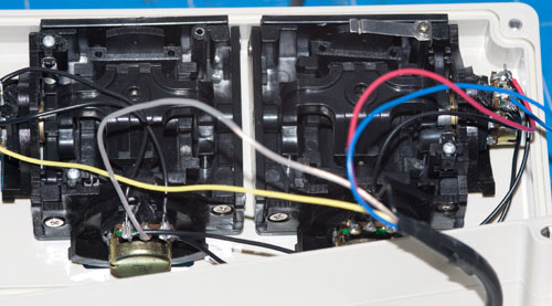
For the rear of the joysticks, we are only using 3 of the 4 channels for this project.
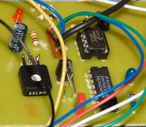
For one of the three PCs for the control box, we had a problem with the PCB layout software getting the output pins on the optical isolators backwards so they had to be mounted vertically and the wires crossed.
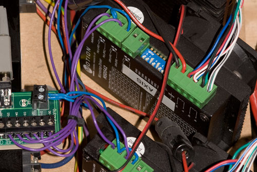
The mill motor controllers with the computer's parallel port connection are visible on the left side.
Comments