
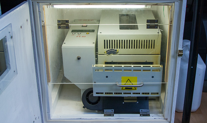
When building our Raspberry Pi development boards we use lead-free solder paste and a C.I.F FT02 batch reflow oven to cook the boards.
The C.I.F promotional videos show the oven being used on a workbench without any fume extraction but after our oven arrived we found after the first board cook that the fumes the oven gives off are far too strong and dangerous to use when in the room without all the window open.
To contain and extract the fumes from the reflow oven we built a wooden box (see bottom photo below) and this has a high-temperature extractor fan which goes through a filter and is then vented outside.
The current extraction fan and box works ok when the oven is running but when changing the cooked boards we get a lot of fume leakage into the room and the oven has to be force cooled between the board cook sessions as the C.I.F FT02 has to return to 100 degrees C before it can start cooking the next batch.
The end temperature of the cooking cycle stops around 150 degrees C and so we have to speed up the cooling after changing the boards as it takes over 20 minutes to cool naturally if the door is just left open, also after a few cooking cycles it takes even longer as the oven gets very hot overall.
We had been using a small desk fan to prop under the door handle on the oven and that blew cool air under the PCB shelf, this helped to cool the oven but some of the heated air and solder flux fumes coming from the oven blew into the workshop and the fumes are not good for our health!
After a busy week building over 500 boards (around 80 cooking cycles) and several wet days so we couldn’t open the windows we had enough of the fumes and felt ill after each session so we decided to try to find a better solution to firstly keep the fumes inside the box to be removed using the extractor fan and speed up the forced cooling cycle to get the oven ready for the next board cook.
Making the forced air cooling feed
In order to cool the oven between the cooking cycles we feed cool air under the PCB drawer with the drawer partly open, this feeds the cool air under the cooked PCB boards aiding their initial cooling and the air goes into the cooking area and the hot air and remaining fumes are then forced out above the PCB boards and goes up and out of the extractor fan/filters.
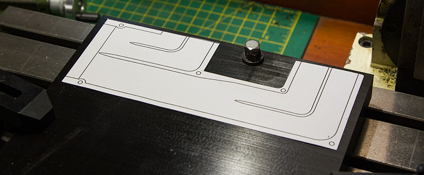
Setting up the material ready to be milled.
We found a 12-volt fan from an old PC server which moves around 1 cubic meter of air per minute and so this was much more than the desktop fan we have used for the past 3 years.
The fan draws around 1.6 amps when running and we have ordered a small mains PSU to run the fan.
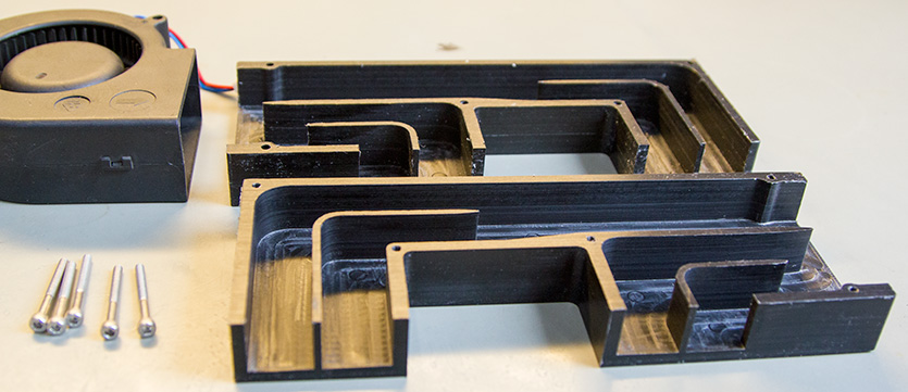
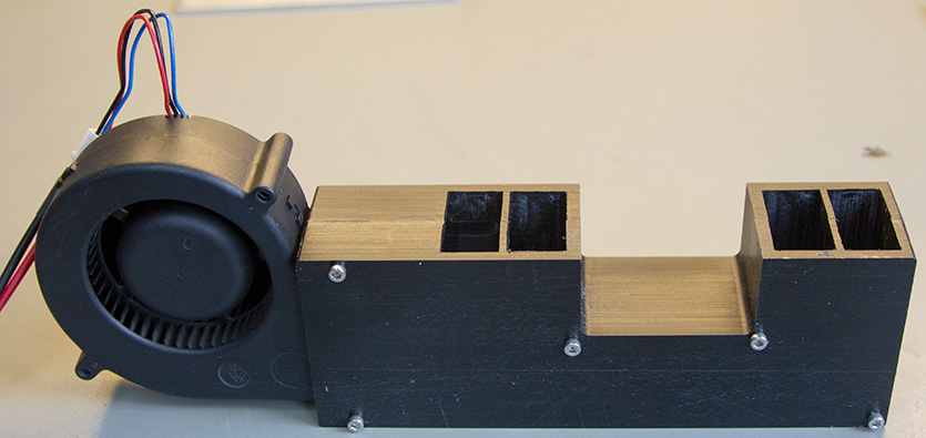
In order to direct the air under the PCB shelf at the correct angle we designed a fan mount and air duct with two air outputs one on each side of the door catch.
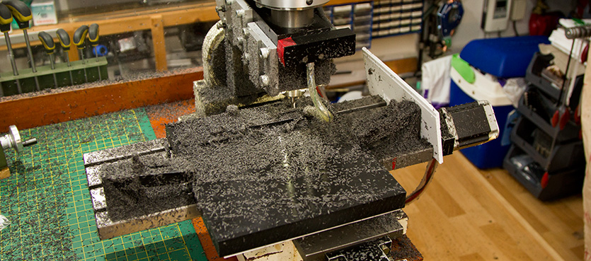
The air ducts were machined from 20mm Delrin / acetal sheet plastic and the two sides were then cleaned, one side was tapped to accept M3 bolts and the two sides bolted together with 30mm M3 bolts.
Cutting the acetal sheet and lots of small chips which stick to everything in the room!
The fan is held in place with two strips of sticky pads and is a very tight fit in-between the sides.
After testing the airflow we tried the new air duct at different angles under the PCB shelf until we found the best angle for the airflow.
The cut parts and PC fan are ready to be assembled.
We secured the new air duct to the extractor box using a pair of small hinges and this also allows us to fold the air duct forward to clean the floor of the extractor box when needed.
Fan and air ducting are ready to be installed.
Reflow Oven fume extraction box changes
To help keep the fumes inside the extraction box we decided to make a second internal flap door which keeps the top of the extractor box shielded when the main door is open and the cooling fan is running.
We have a lot of small offcuts of clear acrylic from a local sign writer Sign and Print and we cut a section to go at the top of the extractor box and then a hinged section below which goes down to the handle of the oven door when it is partly open.
The new second-level door and flap were installed on the extractor box.
The flap door is held open using a pair of powerful magnets which came from old hard drives.
One of the magnets is screwed onto the top of the box frame and the other has been glued onto the inside of the acrylic sheet. When the flap door is open there is around a 10mm gap between the magnets but they are powerful enough to hold the door securely open when changing the PCB boards.
We ran a couple of cooking cycles with the new flap door and cooling system and the cooling times between each cooking cycle is now much shorter, the new door is keeping the fumes inside the box and they are removed by the extractor fan/filters.
The design files can be downloaded in PDF format.


Comments