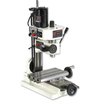
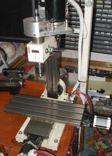
Our original milling machine has undergone several modifications since we purchased it.
First was a new longer bed and then a DIY CNC conversion with the control box being relocated, and in December 2009 we purchased a belt drive kit to make it quieter to use. This was followed by an RPM monitor a couple of weeks ago using an optical sensor.
The one thing the mill has always needed was to be made more precise for CNC milling and the original lead screws had too much play in the threads to enable us to work with small tolerances. We had planned to get ballscrews and ball nuts when we first did the CNC upgrade but they are very expensive to buy and had difficulty obtaining the sizes we needed.
Last week a pair of 8mm shaft ballscrews with 18mm ball nuts appeared on eBay for under £100 so we purchased them to upgrade the X and Y axis on the mill. We will upgrade the Z axis later but we are looking into alternatives for the current cast iron column and runners.
Under the X and Y axis beds is approximately 20mm of clearance to fit the new ball nuts so there was little room for error.
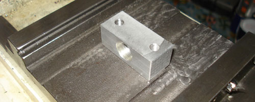
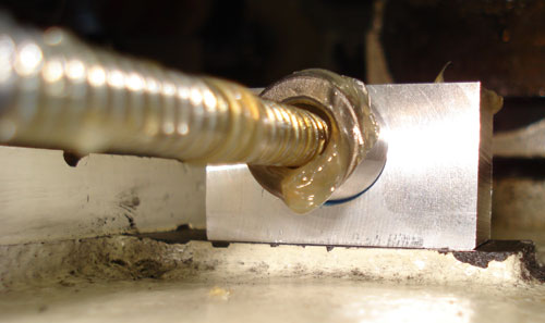
We replaced the old steel nut mounts with new aluminium versions which were tapped to 15mm for the ball nuts.
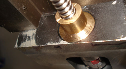
The ends of the ballscrews were turned down to 6mm diameter using the lathe to fit new brass ends to fit against the thrust bearings.
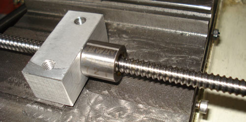
Once the ball nut mounting block was checked, we partially assembled the X-axis to measure the length of the ballscrew with the thrust bearings and motor coupling fitted. The other end of the ballscrew was then trimmed and turned to a 4mm diameter and a small bearing was fitted to steady the shaft at the far end.
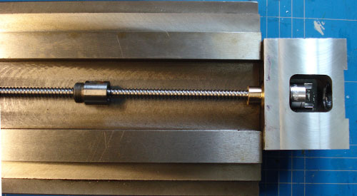
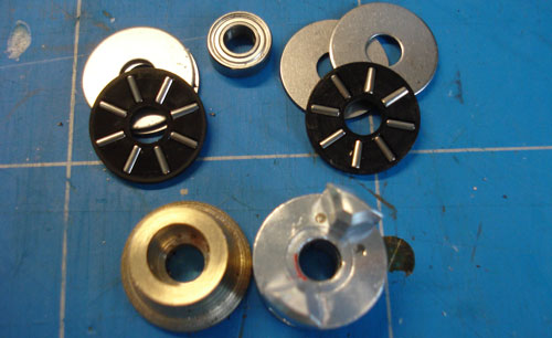
New thrust bearings were ordered from Simply Bearings in the UK, a pair of 19mm outer, 6mm inner thrust bearings and a single 8x3x4 bearing for support. The brass part in the lower left of the photo fits on the turned end of the ballscrew to fit better against the thrust bearing face. The motor coupling fits against the other side of the thrust bearings inside the motor mount to stop left-right movement.
The lower ball nut mount was made to replace the older steel nut and this was approx 4mm higher than the top mount.
Initial tests show that the mill can now move at over 3 times the previous speed using normal lead screws when cutting.
The mill was purchased from Axmister tools and new materials from eBay and other metal suppliers.
Karol
Hi,
Do you remember the part number for this ball screw/ball nut set? As I can see in one picture ball nut is labelled as Hiwin 721.
Brian
Hi Karol, I am sorry but I don't remember the part number. I purchased them from eBay from a Chinese seller.
Chris j
People,i had one and if you add up all the supposed upgrades.its cheaper to get a proper mill instead of a toy,i actually spend and extra £600 when if i sold and added this money another more substantial mill was in my reach,later sold for less than expected and was gutted when i bought an TOS FNK25A TURRET MILLING MACHINE for £1200 and was gutted i spent so much on a less than hobby tool mill..i loved it at first but as you progress you find that the sx1 or what ever you want to call it.is not up to the job that us hobbyists want..but i did love the size which is what drew me to it in the first place..