As part of the solar hot water system, we have been installing in our home we wanted to be able to keep track of the time the solar water pump is running. To monitor the pump we decided to use a simple mains power supply to switch an Opto isolator which then is monitored by the Arduino board and the new logging code which takes a measurement every 15 seconds.
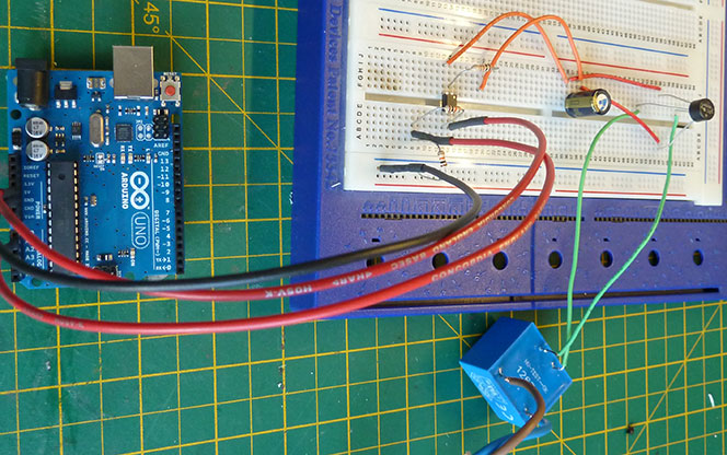
The circuit was initially mocked up using a breadboard and the mains transformer was soldered directly to a mains supply for testing. We used our spare Arduino UNO board to test this circuit as these are much cheaper to replace if we blow one up!
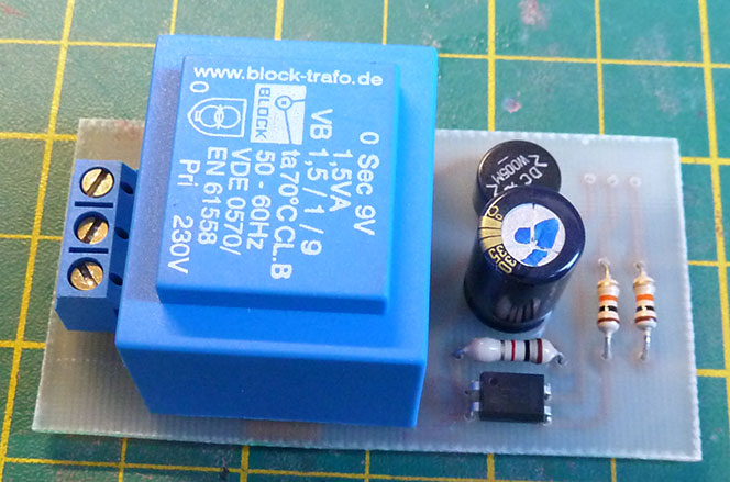
We designed a simple PCB to hold the pump monitor. The circuit is a basic power supply using a small 9v transformer which a bridge rectifier, smoothing capacitor, current limiting resistor and an optoisolator. The low voltage (data) side has a 5V input, Ground input and output pins. The optoisolator input is connected to the 5V line and there is a current limiting resistor for the output line and a pull-down resistor to ground.
On the Arduino board, this was connected to one of the analogue inputs and a simple sketch was written to check the input value and switch between the "Pump On" and "Pump Off" states.
Comments