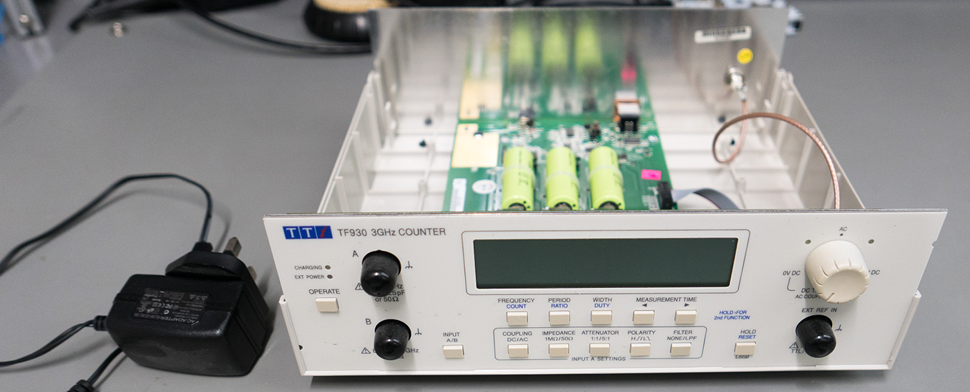
We have an Aim-TTi TF930 3GHz Frequency Counter on our test equipment shelf and this uses an external plastic plugin power brick to power the frequency counter.
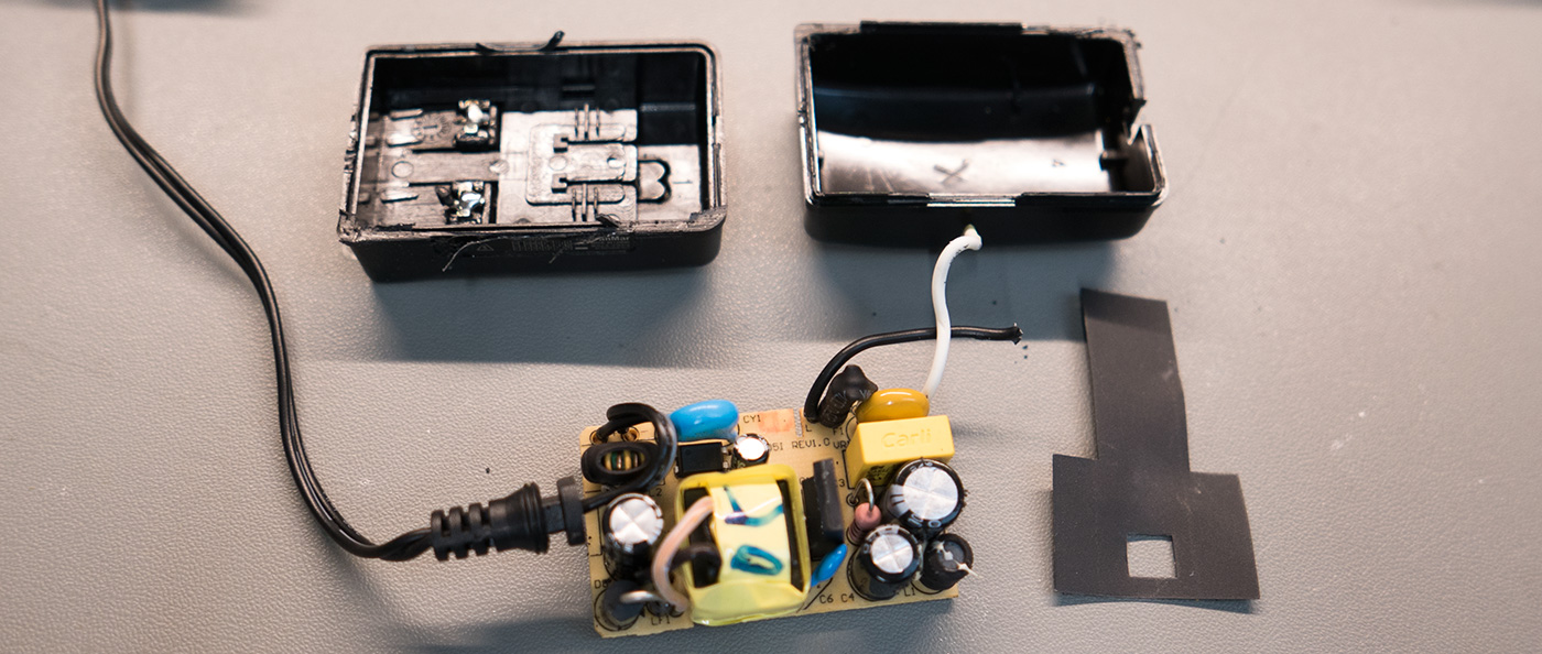
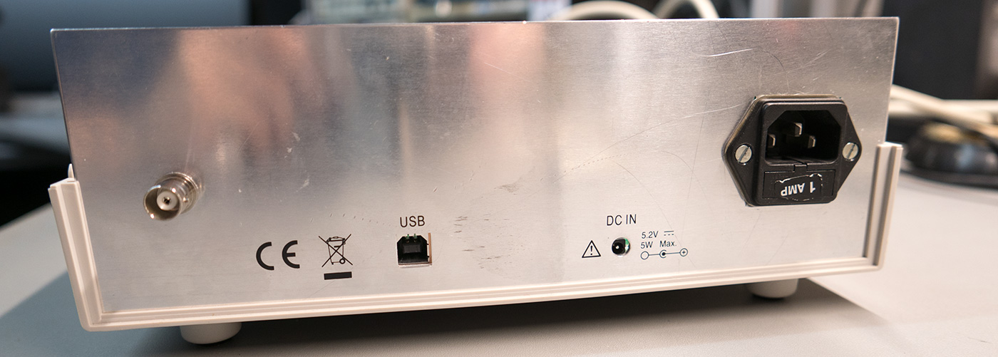
After cutting the plastic case from the power supply we found a simple switching circuit and we decided to install this into the case and add an IEC mains socket with a fuse into the back panel of the case.
We found a filtered IEC mains input socket with a built-in fuse holder which we could use with an IEC mains distribution board which we purchased at a local radio rally earlier this year.
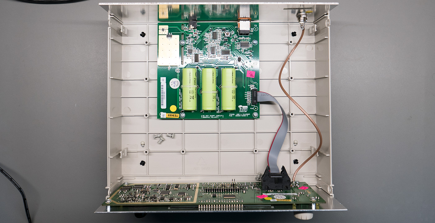
We cut a square hole in the rear panel and mounted the mains socket and bolted the socket using two M3 bolts. The power supply board was then soldered in place and fixed to the plastic case using 2-part epoxy glue.
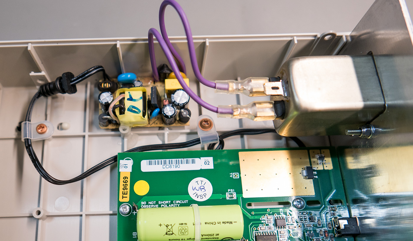
The output from the power supply module was then soldered to the base of the rear PCB under the power input socket.
With the new location of the power supply, the audible whine has gone and the internal location doesn’t seem to have caused any heat or interference issues with the counter.
Power Distribution Changes
All of our mains-powered test equipment and power supplies have always been plugged into separate wall sockets in the past, but we wanted to be able to switch all of the equipment on and off using a single switch. This is partly to reduce the number of sockets being used from ten to one and to turn off the equipment that draws a standby current when not in use.
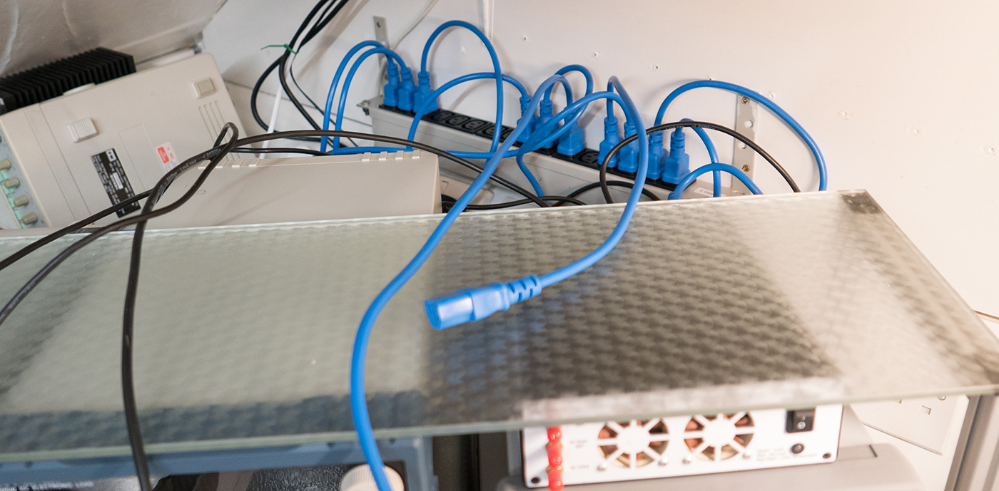
The new IEC distribution board allows us to have all our mains-powered test equipment connected to a single socket. I purchased 10 IEC extension cables, 5 x 50cm and 5 x 1m from Amazon and these replaced the IEC cables which were supplied with the test equipment when new.
We have a HOPI test meter which we purchased from aliexpress and we tested the power consumption of all the test equipment and power supplies when under full load and this was found to be well below the 13 amp maximum a UK mains plug can supply safely.
When all the equipment is connected but turned off or on standby, the internal power supplies are drawing between 25-30 watts so being able to turn it off using a single switch will give us a small power saving on our electric bills.


Martin
Hi Brian, nice mod, will do the same with mine. I have a question: What is the BNC coming to the back of the unit for? I assume 10Mhz ref input? Also I guess you should have ground the back aluminium panel :/ Thanks for your answer
Brian
Martin, the rear BNC is connected to the front external reference input and is grounded via the coax.
Martin
Thanks for your answer, please can you post a link to the IEC power strip ? looks like a great idea
Brian
Martin, I am sorry but I don't know the model as it was one we took from a old power supply.