We are upgrading our DIY PV off-grid system with extra panels and also a solar hot water system using a kit from http://navitron.org.uk/ with a 20 tube 58mm double wall evacuated tube solar collector on the roof and a new water cylinder and Navitron TDC3 Solar Controller to run the hot water system. The new water pump will run from our existing PV inverter and the controller will be on the normal mains supply as this uses very little current.
We plan to monitor and log data from both the PV and hot water systems using an Arduino-based system which will log current, voltage and temperature sensors.
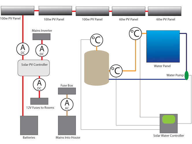
The image below shows the main components of both systems and the monitoring points for the water and PV data.
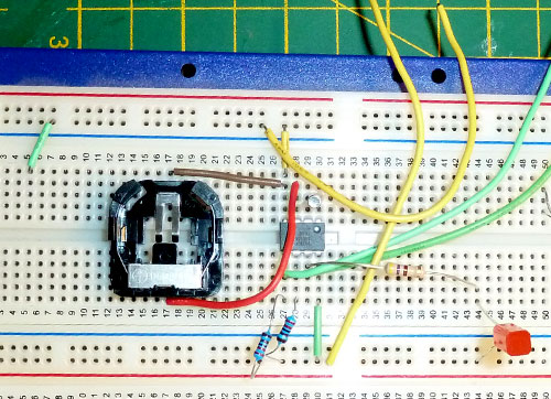
The Arduino board will use a real-time clock and also an Ethernet board to allow the data stored on the SD card to be read remotely. The Arduino did not have a real-time clock fitted as standard so we made a test version using an RTC1307 - Real Time Clock IC and using sample code from http://combustory.com/wiki/index.php we were able to program the clock to the current time.
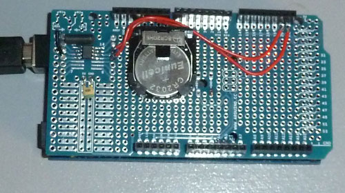
The circuit was then recreated using a surface mount version of the RTC1307 chip and fitted to a blank Arduino shield board as shown below:
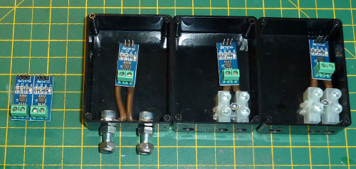
Current monitoring will be performed using 30 amp-rated ACS712 Current Sensor Modules which interface with the Arduino board via the D-A inputs.
The photo below shows three of the board's fitted into boxes and two spare sensors on the left.
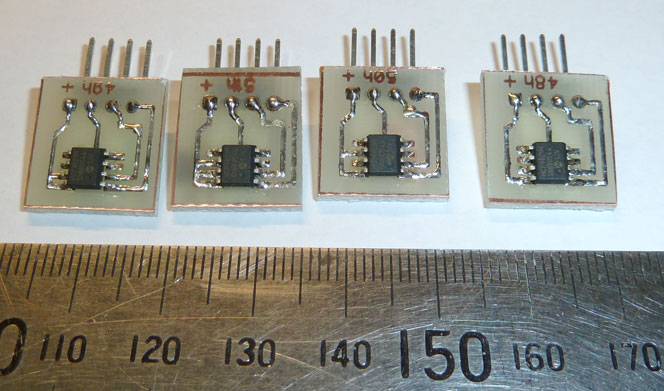
The temperature sensors will be using MCP9801 sensors as shown in the programming socket below.
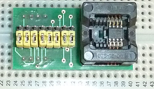
They will connect to the ITC bus on the Arduino board to log the temperatures.
The PCBs were designed using the free version of Diptrace and then the design was transferred to some single-sided PCB using iron transfer sheets. The temperature sensor chip has its internal address assigned by putting 3 of the pins to either 5V or ground so each board was designed to have a unique ID.
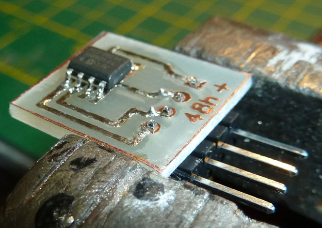
The boards were then etched and cleaned prior to being cut into the individual PCB and the MCP9801 temperature sensor was soldered in place.
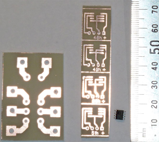
The MCP9801 temperature sensor was soldered to the board and a strip of 4 way edge connector was added for the connecting cables.
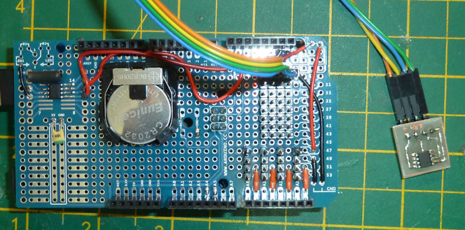
Each board was then tested on the Arduino and using the custom shield with the RTC (real-time clock) and new sets of connecting pins for each of the external sensors.
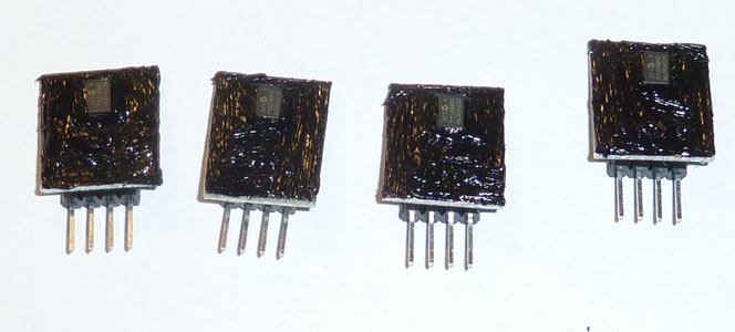
The completed PCBs were cleaned and ready to be painted with a protective coat of high-temperature silicone to protect them when fitted next to the water pipes and hot water cylinder.
The completed PCB temperature sensor boards.
Comments