We use 12 Volt sealed lead acid batteries (SLA) for many different uses from shed lighting to running radios and other 12V equipment which needs a portable power supply.
To check the charge status of the batteries we usually use a multimeter but with some being used as shed lighting on our allotment it would be useful to have a built-in voltage tester fitted on the batteries so we don’t need to carry a multimeter with us each time.
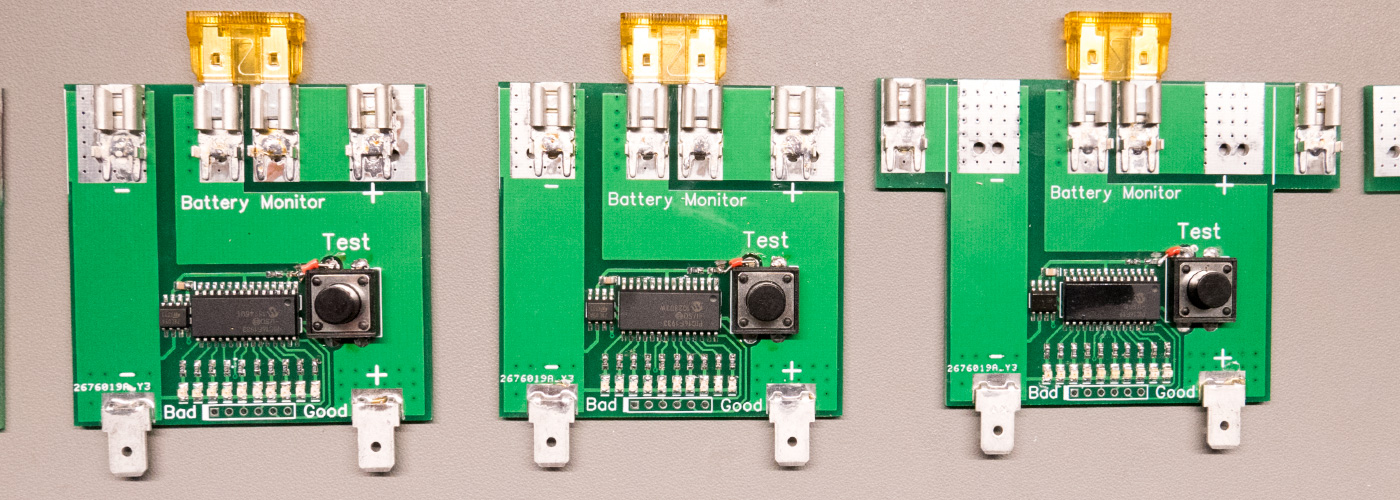
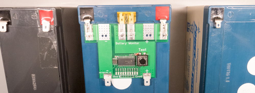
We mainly use the 12 Volt 7 Amp and 12 Volt 12.6 Amp batteries and so Andrew designed a custom PCB which fits directly onto the top of the batteries and has a voltage tester circuit with LED indicators for the charge state.

The circuit uses a Microchip PIC16F1933 with a 5V 78L05 voltage regulator to power the microcontroller and a voltage divider is used to drop the voltage down to a level that can be measured by the internal ADC. A row of 10 LEDs is used to display a voltage range of 11.6V to 12.7V. The LEDs are coloured red, yellow and green to make it quick and simple to see the charge state of the battery. Green means the battery is still charged, yellow means it is getting low and red means it needs recharging.

The tester PCB also has a vehicle blade fuse to protect the circuit and any connected devices.
To operate the tester the push button on the top is pressed powering the PIC microcontroller. The voltage on the ADC input is read and compared to a set of predefined voltage ranges and the battery charge state is then shown on the row of coloured LEDs. There was a layout issue with the batch of PCBs which we ordered, where the ADC input was on the wrong side of the push button. This meant that the microcontroller was being powered through the ADC input even when the button was not pressed so it was always drawing a small current. This was corrected with a link wire between the test switch and the microprocessor and the PCB design was updated for any future boards.

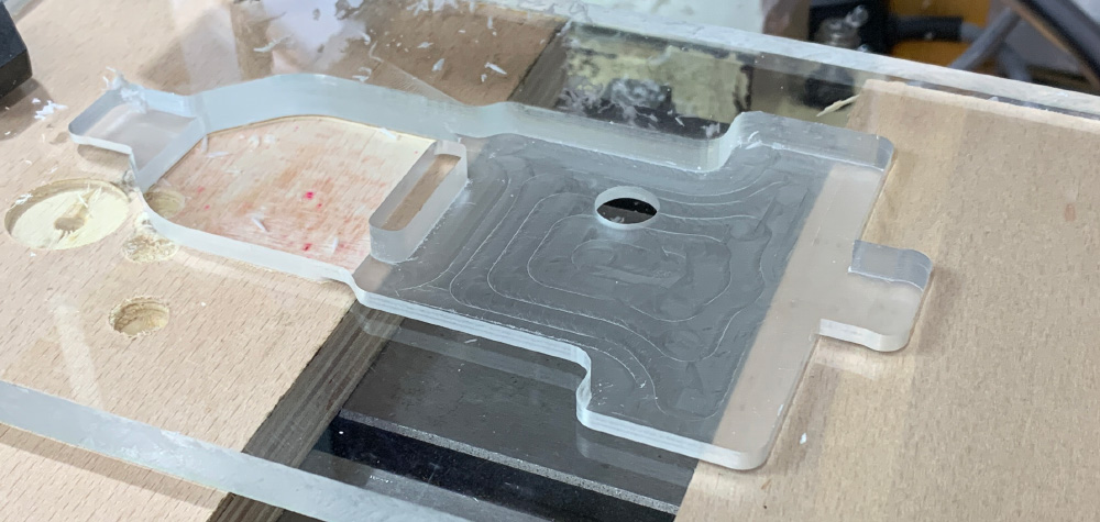
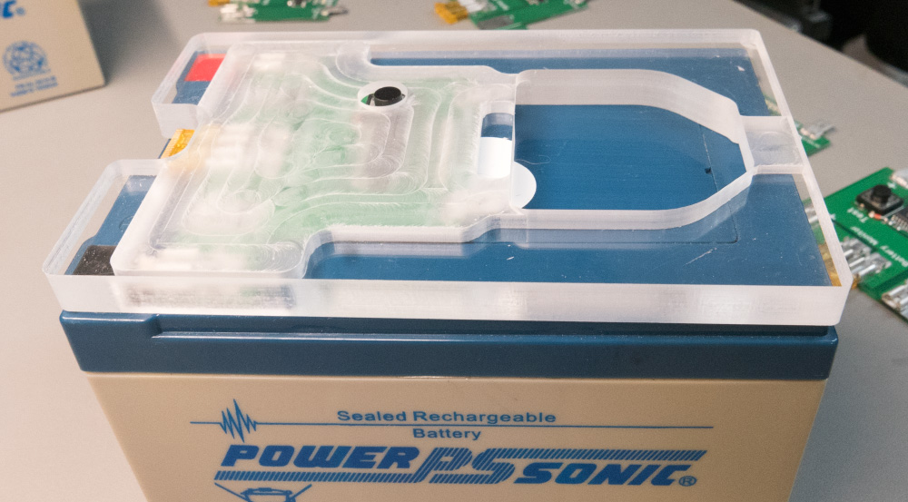
To protect the circuit, we machined a cover from a 10mm thick clear acrylic sheet, and this was milled to cover the top of the battery so they can be stacked on each other if required. This also protects the test switch which is recessed into the top.


The PCB design files in Diptrace format and microprocessor code can be downloaded from GitHub.

Comments