Several months ago we purchased an FE-5680A Rubidium Frequency Standard from eBay, part number P/N 217400-30352-1. We planned to use the frequency standard as a reference for our frequency counter, spectrum analyser, and our HackRF One SDR radio which has the option for a square wave external reference input to improve the stability of the radio.
The FE-5680A Rubidium Frequency Standard runs from a 15V and 5V power supply and has outputs for a 10Mhz sine wave, 1 PPS (pulse per second), and a lock status that goes low when the output frequency has locked internally.
In order for us to have multiple sine wave outputs and also to have a square wave output for the SDR radio we needed to be able to filter and change the output levels of the 10Mhz sine wave signal from the frequency standard.
The output from the unit was approximately 0.4V RMS and we needed to be able to change this for the outputs to the frequency counter and spectrum analyser and also convert it to a square wave for the SDR. We also wanted to be able to use the 1PPS output for external triggering.
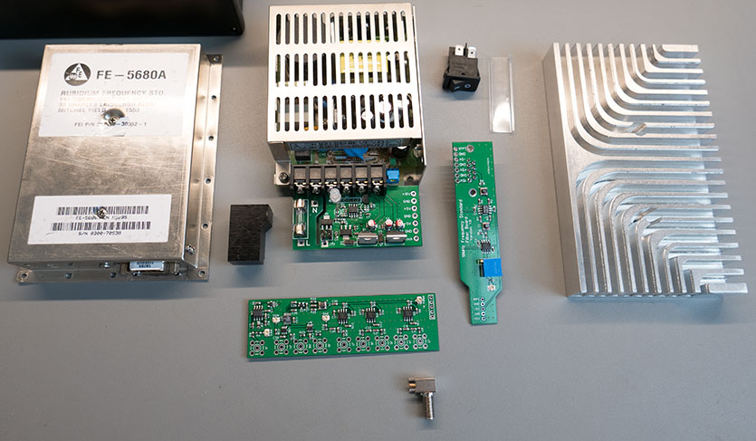
PCB boards ready to be assembled
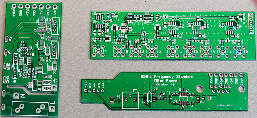
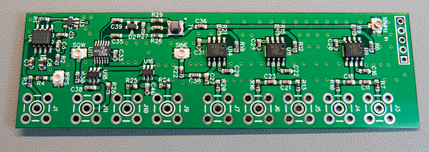
Distribution Board with a sine wave, square wave, and 1PPS outputs
Filter board to connect to the frequency standard.

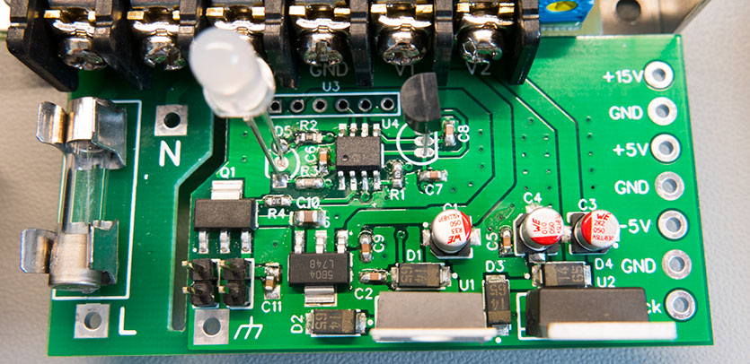
Power supply board with fan control and status led (temperature sensor and led fitted for testing)
The 10Mhz signal from the frequency standard had several strong harmonics which can be seen in the testing section below and we wanted to filter this to remove the unwanted frequencies before we distributed the signal.
We initially tried several active and passive filters using a mix of R/C networks and L/C low and high pass filters and then using active filters using op-amps but none of these gave us the sharp cut-off we needed without degrading the 10Mhz signal.
We then found a LT6600CS8-15 single-chip active filter from Linear which appeared to be suitable for our needs. The LT6600CS8-15 is a low pass filter with a cut-off frequency of 15MHz. Perfect for reducing the second and third harmonics at 20MHz and 30MHz.
After the 10Mhz signal has gone through the low pass filter it is amplified by an op-amp which has a multi-turn potentiometer to set the gain level. We decided to use a potentiometer as this would allow us to adjust the voltage once the project is complete. The signal is then connected to a distribution board via a short coax cable where it is split and buffered to the 50-ohm sine wave outputs using LM7171 op-amps.
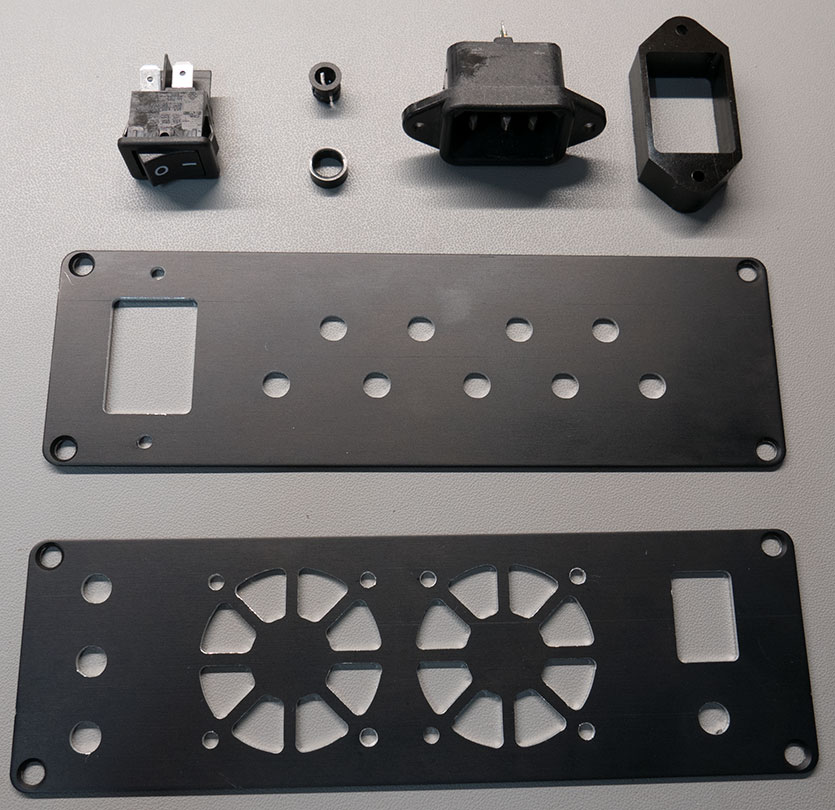
The case front and rear panels are milled for the sockets and connectors.
The pulse on the one pulse-per-second output from the FE-5680A is only 1uS long. This was too short to be easily captured on our oscilloscope and might not be long enough to trigger some external equipment so we decided to make the pulse longer by using a 555 timer. The 1PPS output is connected to the distribution board via a ribbon cable and the pulse length is changed using a 555 timer chip in monostable mode. This gives a pulse length of 10ms which can be used by external devices.
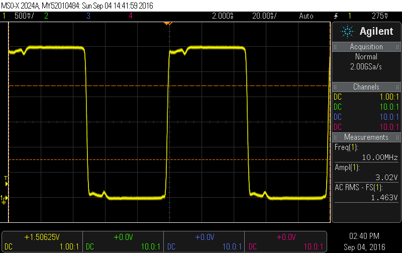
The sine wave is converted to a square wave using an LTC6957-3 ic and the outputs are buffered using SN74LVC2G17 dual Schmitt-trigger buffers. After connecting the square wave output to the scope we found that there was initially a lot of noise and large voltage spikes on the signal but we resolved this by using a 50ohm coax to connect directly to the scope instead of a standard scope probe. We then found that the rising edge on each pulse was not very clean and after posting about the problem on the eevblog forum it was discovered that the buffers could not handle a 50-ohm output and were not rising fast enough. It was recommended that we connect the multiple buffer outputs together to reduce the problem.
This has resulted in us only having a single square wave output but at the moment we only need one for the SDR radio and so if we need any additional outputs in the future we can build a new version of the distribution board with the additional buffers in parallel for each of the outputs.
Internal parts are ready to be connected and installed.
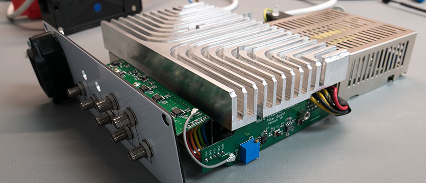
Mockup outside of the case with the power, filter and distribution boards connected.
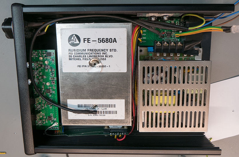
The boards and parts are fitted to the case.
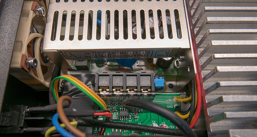
The fans have been installed into the front panel and the mains switch is on the lower left of the photo.
Everything is installed, next the lid will be milled to let the hot air out of each side.
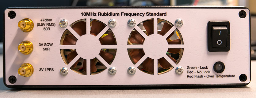
The front panel of the unit with a label fitted.
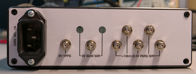
The rear panel of the unit with a label fitted. The label has squashed next to the mains socket but as this is on the back of the unit we will leave it as it is.
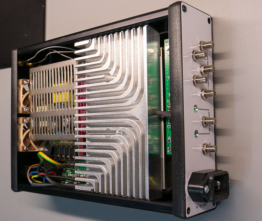
The power is supplied by a dual output switching PSU module from Traco Power and it has +15V and -15V outputs.
These are connected to a custom power board that connects directly to the power supplies inputs and outputs and has a mains input with a protection fuse on one side and the low voltage side is protected by a spark gap slot.
The power board has three regulators to bring the +-15V down to the levels required for the circuit. We used a +5V regulator for the frequency standard and the filtering and distribution boards, a -5V regulator for the filter and distribution boards, and a 12V regulator which powers the cooling fans.
The fan and front LED are controlled by a Microchip PIC12F1822 microcontroller which monitors the heatsink temperature using an Analog Devices TMP36 sensor which connects to the ADC input in the PIC and the lock pin from the frequency standard is connected to one of the PIC’s IO pins.
The microcontroller monitors the heatsink temperature and then controls the fan speed via a Darlington transistor using PWM to vary the speed. After building the power board we found a mistake with the circuit and the NPN transistor was on the wrong side of the fan. A careful cut of the PCB track and the addition of a link wire solved this issue.
To give additional cooling for the frequency standard we machined a custom heatsink from a block of 20mm thick aluminium which took approximately 6 hours to cut. You can see a video of the cutting steps on my YouTube channel at https://www.youtube.com/watch?v=Uq236Mt4dIc
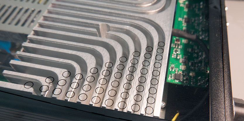
We had planned to add a cutout to the case cover to allow the hot air to escape but after a failed attempt to mill the cover, we decided to use a series of drill holes. The photo below shows the template on clear plastic to check the alignment.
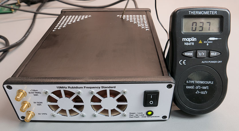
The finished unit with a thermometer sensor in the heatsink to check the internal temps.
Testing and output waveforms.
The frequency output from the frequency standard has a lot of harmonics when connected to our spectrum analyser.
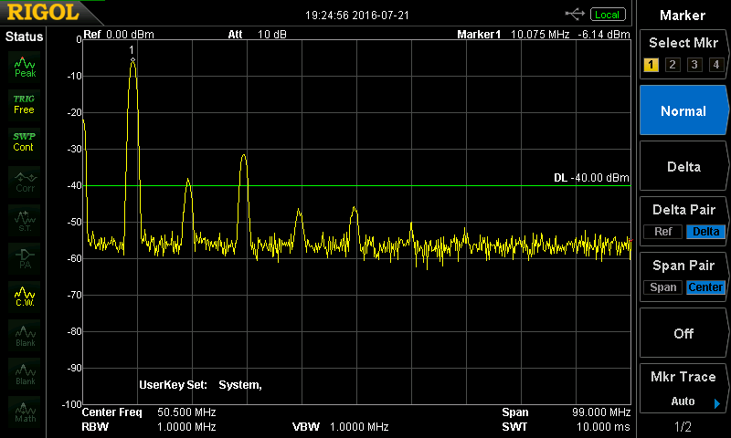
This was corrected by the filter on the new filter board.
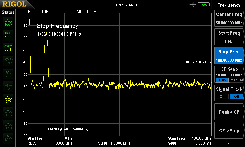
Square wave output when using a standard scope probe with an earth lead clipped to the case showed a lot of spikes on the signal, after some research online we found this was due to inductance on the scope leads causing the extra ringing.
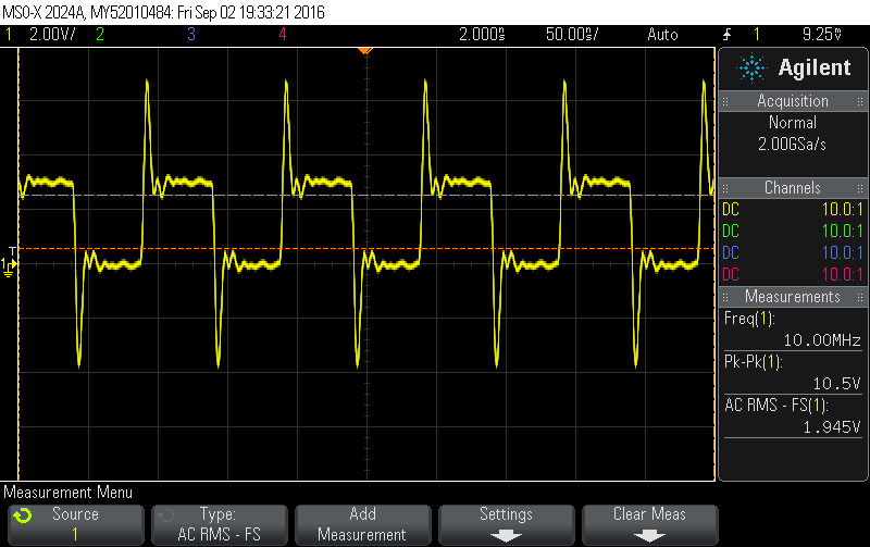
After using a different test lead and combining the output channels the unwanted signals were reduced to a usable level on the SDR.
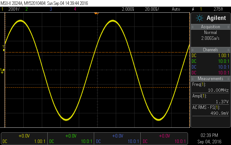
And the sine wave output on the scope
The code and PCB files for this project can be downloaded from GitHub at https://github.com/briandorey/10Mhz-Frequency-Standard-Distribution-Project
roadrunner
Hello , thank you for really nice project, i am doing my distribution board based on LM7171, i am really interested to know how your distribution amp goes with 50Ohm load, because for LM7171 has really low output swing with low load resistance , with two 50ohm load connected, achieving 7dBm level swing with 10V supply is kind of nice. i will be waiting for your reply. Thank you in advance.
Loïc
Hi,
As a time nuts aficionado, i have some projects around especially dedicated to phase noise measurements.
A bit interested by your enclosure, i would like to know if you have a CNC or just a milling machine (I own a little one for that purpose ), and I suppose that the label is processed by a vector printing cutter ?
regards
Loïc
Brian
Hi Loïc , We have a small DIY converted milling machine https://www.briandorey.com/post/axminster-sieg-super-x1-micro-mill-ballscrew-upgrade-and-modifications and the printing was done by a local sign business who has a full colour vinyl printer and a cutter.
Josh
Hi Brian,
I am curious as to why you chose to not use 510 ohm resistors for the feedback resistors in the LM7171 circuits, as per the datasheet recommendation?
Regards,
Josh
Bojan
Hi, Brian
I was looking for a 10 MHz distribution Amp for my 12V OCXO for some time. I found this project of yours. Took 7805 for +12V to +5V and a 0505 DC/DC for -5V. I am very happy with the result. Your 15 MHz LPF works fine.
I am using 3 x sine out and one square out. I hope you are ok with the fact that I used your gerber files from the github.
BR, Bojan
Rob
Hi, Is there a BoM availabe, can't find it...
I am interseted to know which transformers you used in the LPF filter.
Thanks in advance.
Brian
I have added the BOM for the three boards into https://github.com/briandorey/10Mhz-Frequency-Standard-Distribution-Project
Rob
Thank you!