Earlier this month we experimented with adding our Raspberry Pi expansion boards to the Intel Celeron J4125-based Radxa X2L small form factor computer board.
The Radxa X2L is a powerful compact computer designed for various applications, from desktop computing to IoT projects. The motherboard is approximately three times bigger than the Raspberry Pi and when the PCB is on a flat surface it rests on the M.2 SSD drive so a case was needed to stop any damage to the storage drive and protect the rest of the motherboard’s components.
Designing The New Case
The Radxa website has hardware information for the pcbs at docs.radxa.com/en/x/x2l/hardware/hardware-info and this includes DFX files of the PCB layout and mounting hole locations.
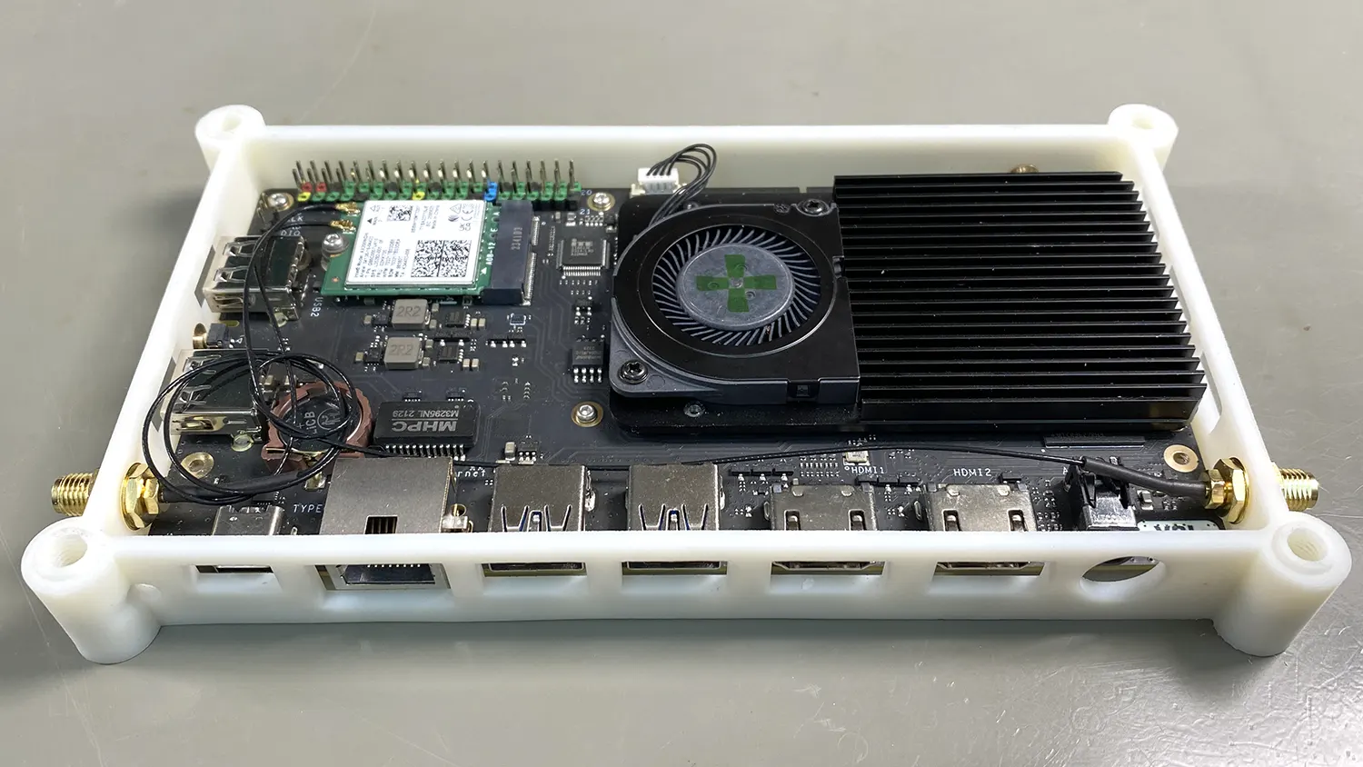
The Radxa X2L motherboard has nine 2mm holes in the PCB to accept M2 bolts and these are used to install the heatsink and fan and to mount the board to a case or mounting panel.
The PCB has a 40-pin GPIO header along one edge and a power button, the left side of the motherboard has two USB 2.0 sockets and a boot select button for the RP2040 chip.
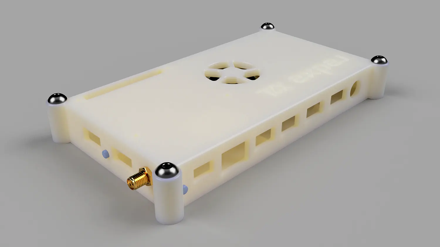
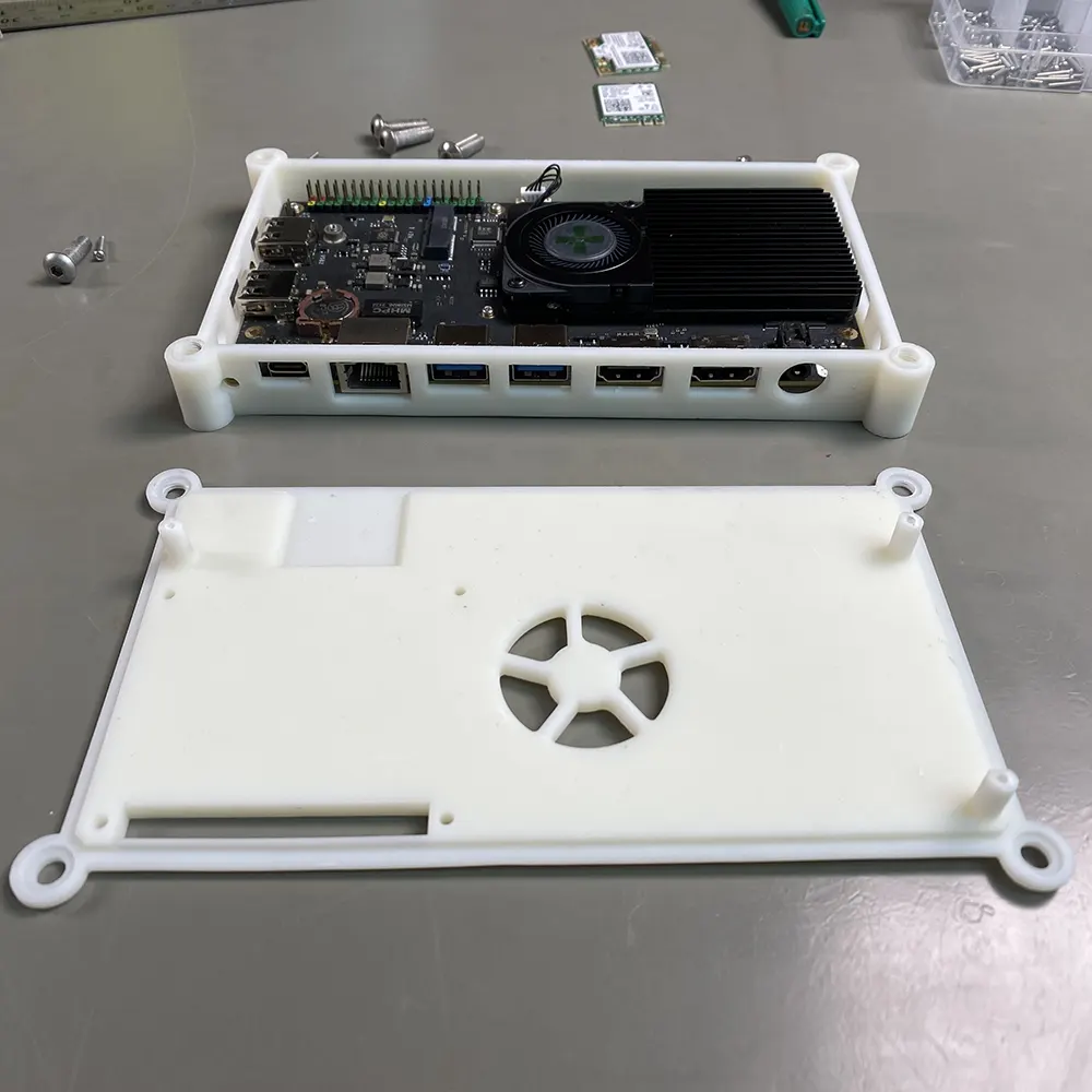
The lower edge of the motherboard has an eMMC recovery button, USB C power socket, gigabit ethernet, two USB 3.0 sockets, two 4k HDMI sockets and a headphone jack with microphone input.
The base of the motherboard has an M.2 connector and a clear CMOS button.
We designed the new case using Fusion 360.
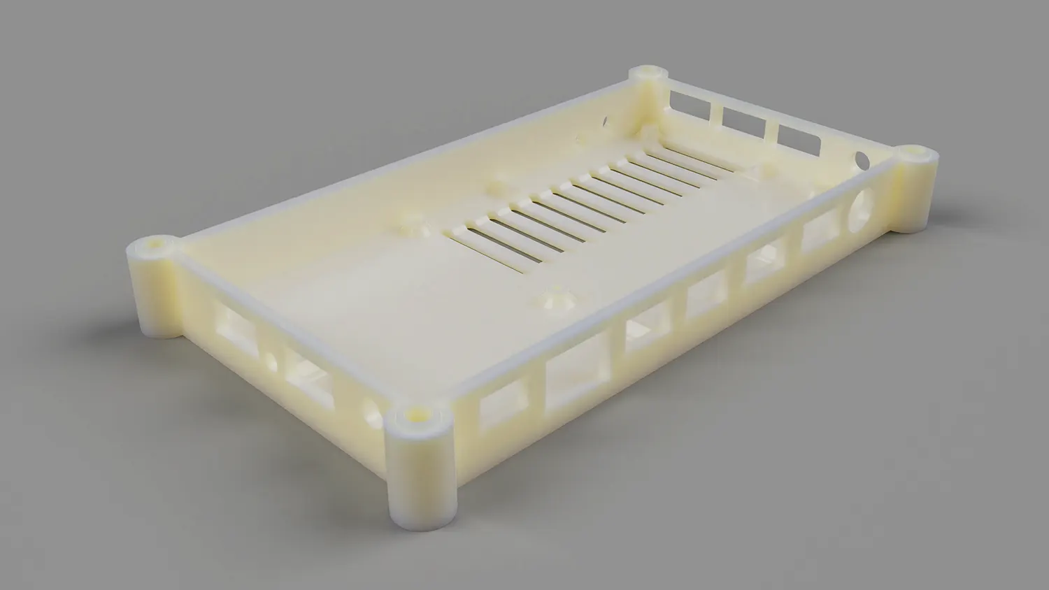
The case is designed in two parts with the base and sides in one part and a removable lid which is held in place using M5 bolts on each corner which go into rivet nuts pressed into the case.
We decided to use rivet nuts rather than heat-pressed inserts as we already had them in stock.
The idea behind using M5 bolts on each corner is that it will allow us to make stackable expansion modules to fit on top of the case that can interface with the X2L through the GPIO header or one of the USB ports. We have not designed any expansion modules yet, but we do have some ideas for future projects.
The PCB is held into the base using three M2 x 8mm bolts and nuts recessed into the plastic and three M2 x 10 bolts which go up through the base and into threaded pillars on the case top.
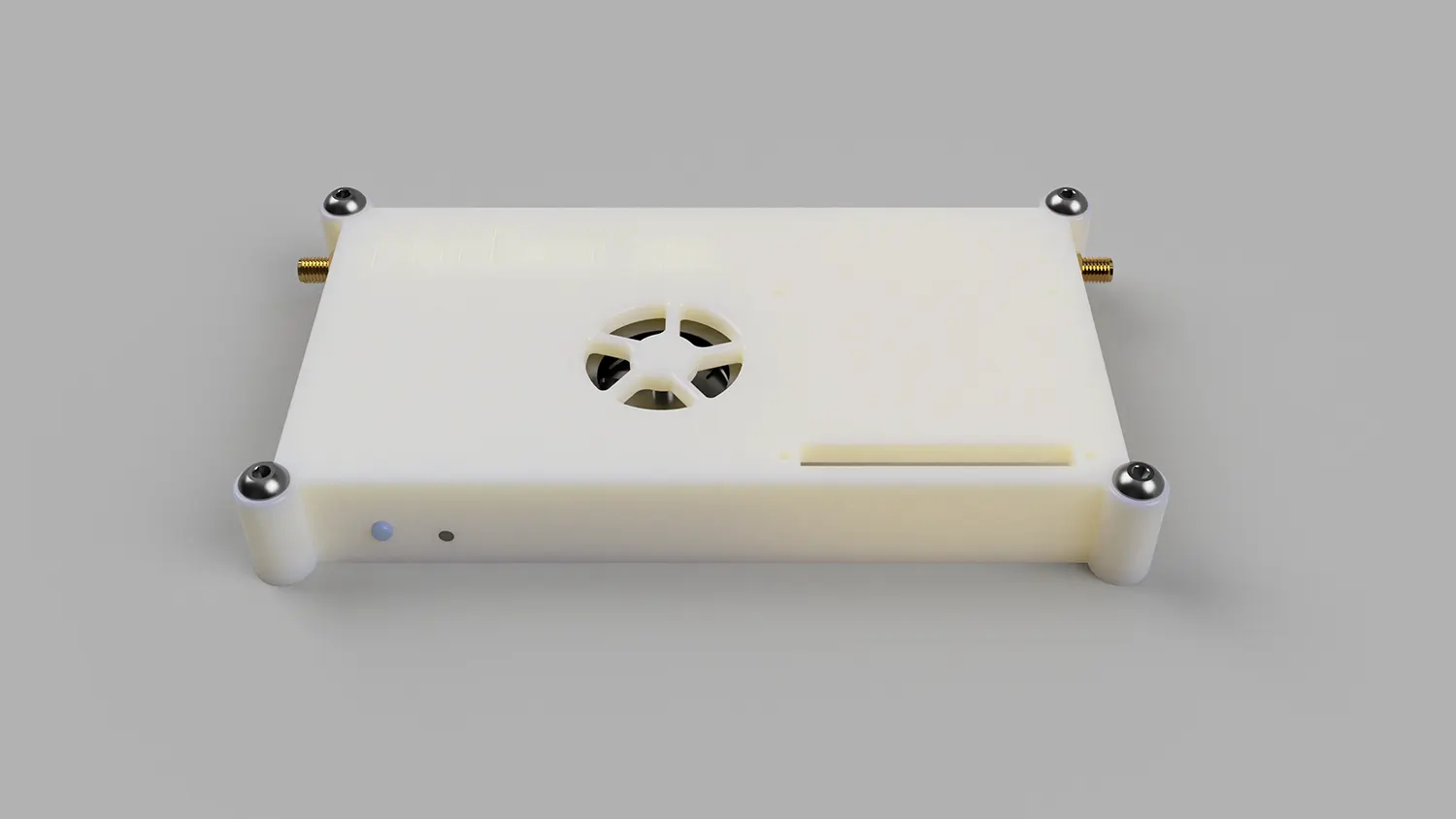
The top of the case has a cutout for the 40-pin GPIO connector and holes to accept M2.5 bolts and mounting spacers to allow the installation of Raspberry Pi hats and expansion boards.
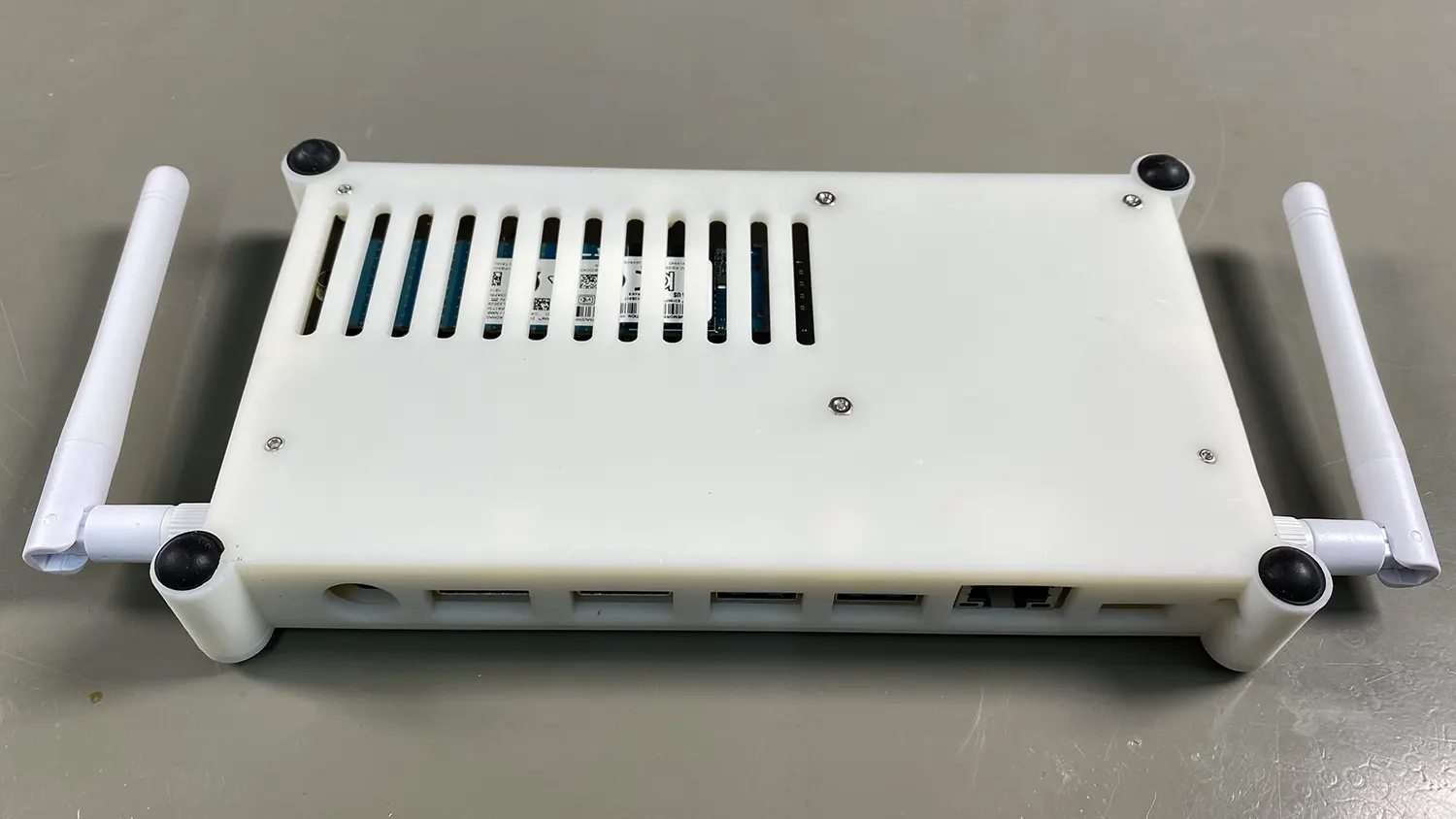
There is also a cutout for the cooling fan intake, and this exhausts the hot air out of the side of the case.
Printing and assembling the case.
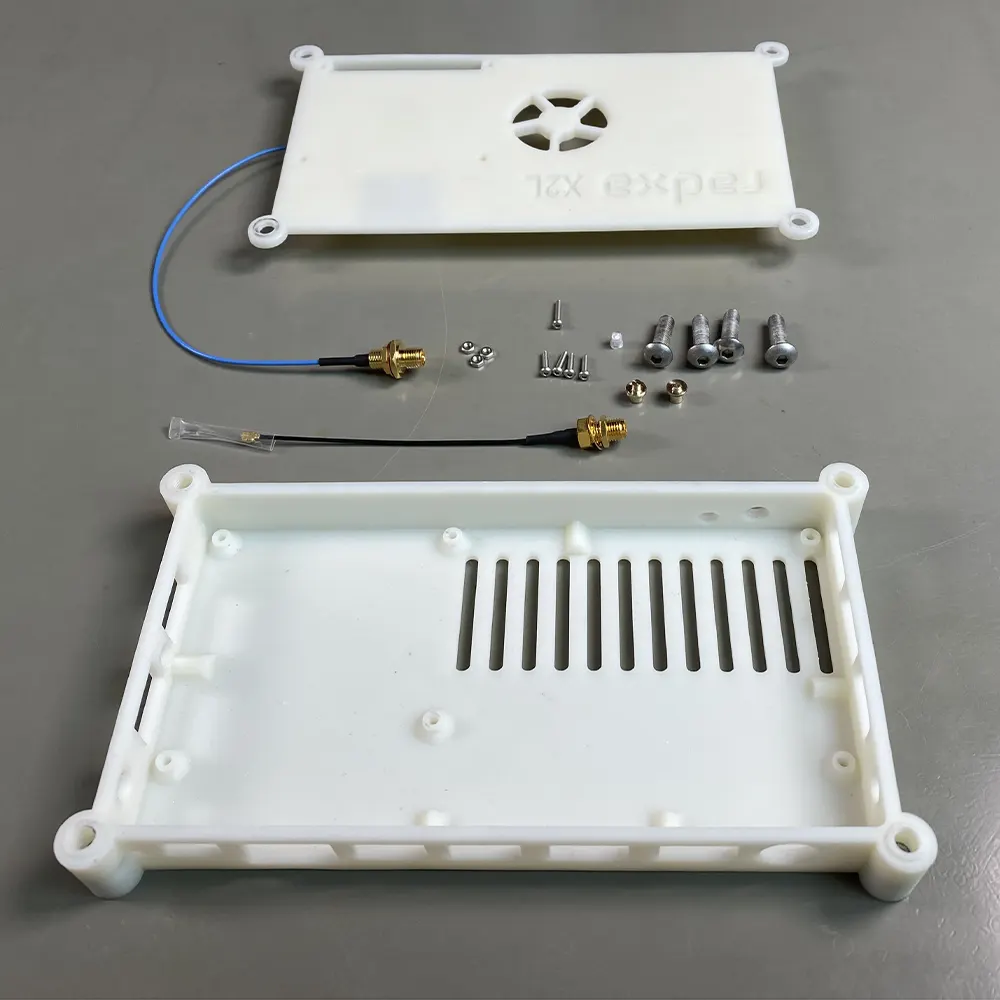
With the new case designed, the parts were exported in STL format and ordered at jlc3dp.com using SLA CBY Resin. The cost was £19.53 including shipping.
After a couple of weeks, the case parts arrived and we found that there was a small amount of warping along the length of the case but with the top clipped and bolted in place, this resolved the slight curve in the plastic.
There were a few small alignment issues with the connectors and GPIO header. These have been fixed in the STL files in our GitHub repository. We also increased the clearance between the NVME drive and the bottom of the case as the memory chips were touching the plastic which could cause overheating problems on some NVME drives.
The pillars in the case top were tapped using an M2 tap, and the rivet nuts were pressed into the corners of the case base.
The case has holes for the power and boot select buttons for the RP2040 chip and we created small buttons using brass rods on our small lathe. These could also be 3D printed if needed.
For the LED power indicator on the PCB, we made a light pipe with a 3mm white LED by cutting off the leads and drilling out the LED components using a 2mm drill. A piece of round 3mm clear acrylic bar would also do the job.
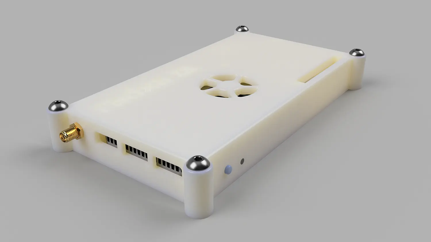
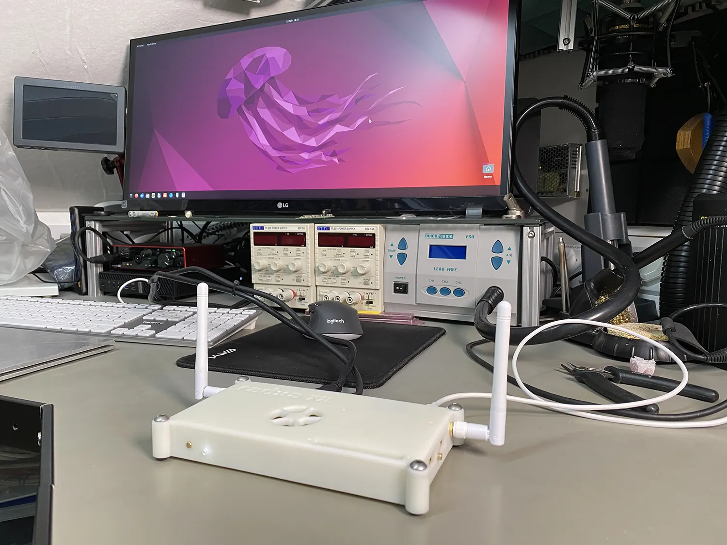
On the ends of the case, there is a mounting hole for an SMA antenna connector, and we installed a Wi-Fi card to the motherboard and short pigtail cables were fitted to the case allowing external antennas to be installed.
Testing the case for temperature issues
After assembling the Radxa X2L into the case we powered it on and tested the CPU temperatures using the Linux sensor application.
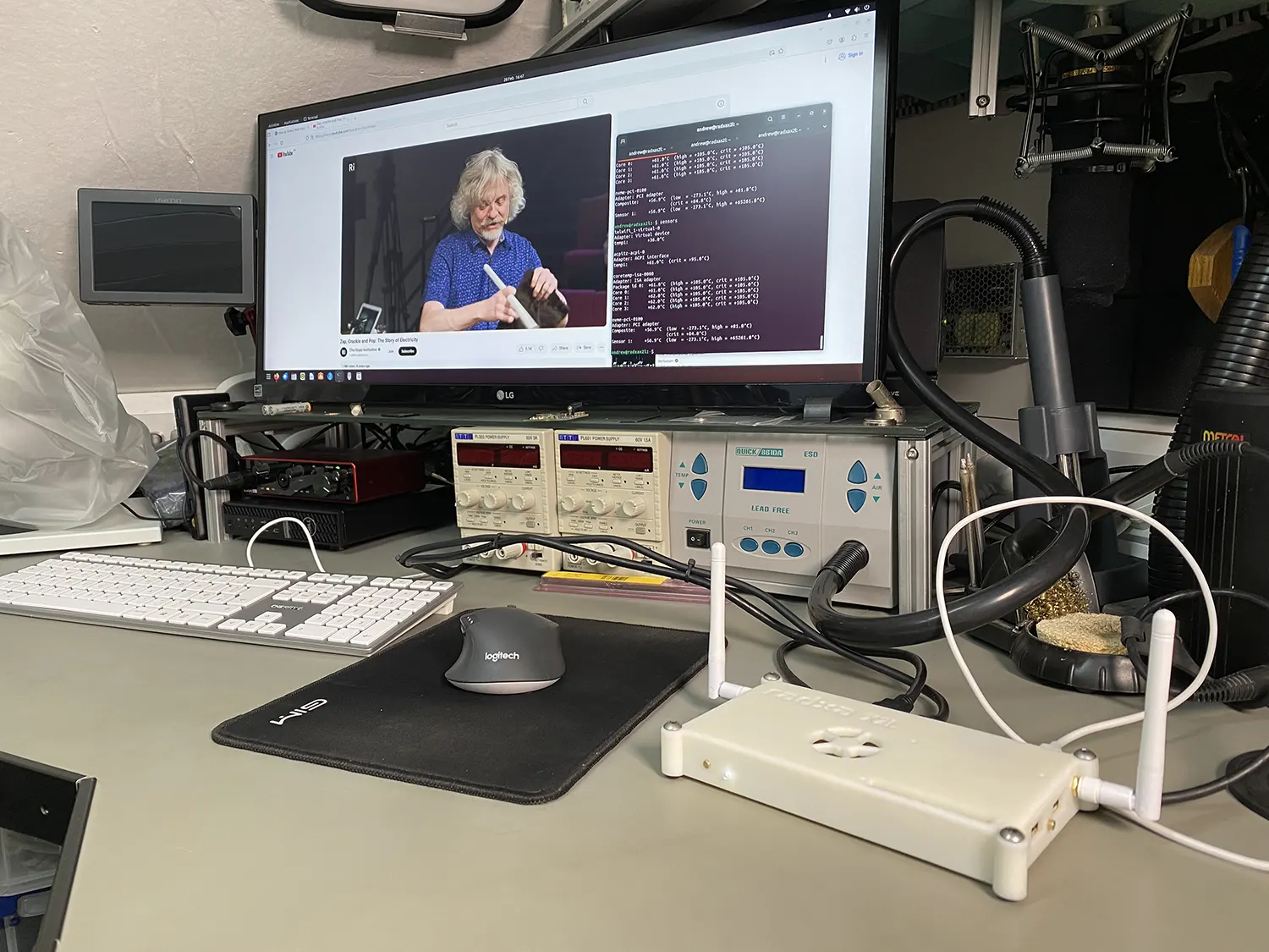
At idle the CPU temperature was 46°C.
To test a high load, we used the stress application "stress -c 8" to run eight processes and watched a 1080p YouTube video.
After 10 minutes the CPU temperature had stabilised at around 62°C. It quickly dropped back down to 46°C when we stopped the stress processes and closed the web browser.
The files for this case can be downloaded GitHub at github.com/briandorey/Radxa-X2L-case
Power Consumption
The following measurements where taken using a HOPI power meter connected to a USB power supply and Wi-Fi enabled, connected to an HDMI monitor with a USB mouse and keyboard via a KVM switch.
| Status | Power in Watts |
|---|---|
| Booting | 5.4W |
| Ubuntu Desktop with HDMI Connected Idle | 3.7W |
| Ubuntu Desktop without HDMI Connected Idle | 3.1W |
| Playing fullscreen YouTube video | 10W |
Parts List
In addition to the 3D printed case, I used the following items to assemble the case and add a Wi-Fi module and antennas to the board.
| Item | Quantity | Purchase Link |
|---|---|---|
| Bingfu U.FL IPX IPEX MHF4 to RP-SMA Female Bulkhead Mount WiFi Antenna Cable 25cm | 1 | Amazon |
| Bingfu External WiFi Antenna RP-SMA | 1 | Amazon |
| WiFi 6E AX210 NGW WiFi Card with Bluetooth 5.3 | 1 | Amazon |
| M2 x 0.4 Spiral Flute Tap | 1 | Amazon |
| 230pcs M2 Bolts and Nuts Set | 1 | Amazon |
Nicolas
Hi,
By any chance, did you measure the power consumption of the board? I'm particularly interested in the idle and headless configuration but couldn't find that information online.
Brian
I have taken power measurements and added them to the post above.