On our AB Electronics website we always had a primary focus on the Raspberry Pi when developing the expansion boards but that does not mean we ignored all the other small form factor that have been released.
We tested the Raspberry Pi expansion boards on a wide range of computer platforms from companies like Orange Pi, Odroid and Asus and if they work together, we add them to the compatibility list on each of the product pages.
One new computer that recently caught our eye is the Radxa X2L. Radxa are best known for their Rock series of ARM based computers that share many characteristics of the Raspberry Pi. For the X2L Radxa took a different approach.
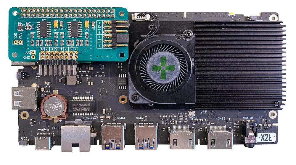
The Radxa X2L is a compact yet powerful computer designed for various applications, from desktop computing to IoT projects. The board is physically bigger than the Raspberry Pi, around 3 times larger and it is powered by a Intel® Celeron® J4125 Processor. Being Intel x64 means it can natively run Windows 10 or the wide range of Linux distributions that are available for x64 based computers.
One of the distinguishing features is the inclusion of the RP2040 microcontroller to control its GPIO header. The RP2040, developed by Raspberry Pi, has a dual-core ARM Cortex-M0+ processor, making it suitable for real-time tasks and peripheral control.
Adding analogue inputs to the Radxa X2L
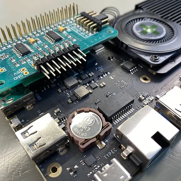
This setup presents a unique challenge for integrating devices like the ADC Pi, an 8 channel analogue to digital converter, which rely on I2C digital communications. The RP2040's microcontroller architecture differs significantly from the typical direct Linux control over GPIO pins found in other single-board computers. This difference necessitates a bridge between the microcontroller environment and the Linux system to communicate with peripherals like the ADC Pi. We looked at several possible solutions to this interfacing problem before finding one that should work reliably and can be modified to suit individual needs.
To allow communication between the ADC Pi and the RP240 to the host processor on the Radxa X2L, we needed to deploy a microcontroller program on the RP2040. This program is responsible for directly interfacing with the ADC Pi, reading analogue values, and then sending these readings to the Linux system via the serial port in a structured format, such as JSON strings.
This approach allows for real-time data acquisition from the ADC Pi while leveraging the processing power and flexibility of the Radxa X2L's Linux environment for data processing, storage, or further actions.
RP2040 Code
The first step involves programming the RP2040 to communicate with the ADC Pi.
We used the ADC Pi MicroPython library for the Raspberry Pi Pico that is available from our GitHub repository at github.com/abelectronicsuk/ABElectronics_MicroPython_Libraries.
The pins for the I2C bus on the GPIO header normally found on pin 3 for SDA and 5 for SCL. On the RP2040 these are connected to pins 28 for SDA and 29 for SCL.
An example MicroPython script can be seen below.
#!/usr/bin/env python

"""
================================================
AB Electronics UK ADC Pi 8-Channel ADC demo for MicroPython Library

Run using Thonny Python IDE from https://thonny.org/

Create a file in Thonny called ADCPi.py, copy contents from ADCPi.py
to the file and save it onto the Raspberry Pi Pico

Create a file named demo_readvoltage.py, copy the code from this file and save
onto the Raspberry Pi Pico

Run with "Run Current Command" or F5 in Thonny

================================================

Initialise the ADC device using the default addresses and sample rate,
change this value if you have changed the address selection jumpers

For the Radxa X2l computer use pins 28 for sda and 29 for scl

The sample rate can be 12, 14, 16 or 18

"""
import time
import json
from ADCPi import ADCPi

def main():
    '''
    Main program function
    '''
    # I2C addresses of 0x68 and 0x69, bit rate 12 with SDA on pin 28 and SCL on pin 29
    adc = ADCPi(0x68, 0x69, 12,28,29)

    while True:
        try:
            # get ADC values
            a1 = adc.read_voltage(1)
            a2 = adc.read_voltage(2)
            a3 = adc.read_voltage(3)
            a4 = adc.read_voltage(4)
            a5 = adc.read_voltage(5)
            a6 = adc.read_voltage(6)
            a7 = adc.read_voltage(7)
            a8 = adc.read_voltage(8)

            # create an array using the adc values
            data = [a1, a2, a3, a4, a5, a6, a7, a8]

            # Create the JSON object with the data array
            output_dict = {
                "board": "adcpi",
                "data": data
            }

            # Convert to JSON string
            json_string = json.dumps(output_dict)

            print(json_string)

            # wait 0.1 seconds between reads
            time.sleep(0.1)

        except:
            # show error message if the read fails
            output_dict = {
                "board": "adcpi",
                "error": "read error"
            }

            # Convert to JSON string
            json_string = json.dumps(output_dict)

            print(json_string)


if __name__ == "__main__":
    main()
Download picoadccode-py.txt and rename to picoadccode.py
An ADCPi object is used to set up I2C communication between the RP2040 and the ADC Pi. A while loop is used to initiate data reads from the ADC Pi's channels, and format these readings into JSON strings.
The program then writes these strings to the RP2040's serial output, effectively turning the microcontroller into a bridge between the analogue world and the digital, Linux-driven Radxa X2L.
On the Radxa X2L
On the Linux side, a Python script like the one shown below can be used to read the JSON strings from the serial port. This script continuously monitors the serial port for new data, decodes the JSON strings, and processes the analogue values for any application needs, from simple logging to real-time monitoring and control.
Here's a basic outline of such a Python script:
import json
import serial
import os
import sys
import time

# Function to clear the screen
def clear_screen():
    if os.name == 'nt':  # for Windows
        _ = os.system('cls')
    else:  # for macOS and Linux(here, os.name is 'posix')
        _ = os.system('clear')

# Setup serial connection
serial_port = '/dev/ttyACM0'
baud_rate = 9600  # Adjust this depending on your device

try:
    ser = serial.Serial(serial_port, baud_rate)
    print("Serial port opened successfully. Reading data...")
    buffer = ''  # Initialize a buffer to accumulate data

    while True:
        data_in = ser.read(ser.inWaiting() or 1)  # Read available data or block for one byte
        if data_in:
            # Decode byte to string and accumulate in buffer
            buffer += data_in.decode('utf-8')

            # Check if a complete message has been received (indicated by a newline)
            if '\n' in buffer:
                # Split buffer at the first newline; [0] is the complete message, [1] is the start of the next message
                complete_message, buffer = buffer.split('\n', 1)

                # Clear the screen before printing new values
                clear_screen()

                # Attempt to parse the JSON string
                try:
                    data_dict = json.loads(complete_message)
                    data_array = data_dict["data"]

                    # Print each value in the data array as separate rows
                    for i, value in enumerate(data_array, start=1):
                        print(f"Channel {i}: {value}")
                except json.JSONDecodeError:
                    print("Error decoding JSON. Check the format of the incoming data.")

except serial.SerialException as e:
    print(f"Error opening serial port: {e}")
except KeyboardInterrupt:
    print("Program terminated by user.")
finally:
    ser.close()  # Ensure the serial port is closed on exit
Open readadc-py.txt and rename to readadc.py
Integrating the ADC Pi with the Radxa X2L via the RP2040 microcontroller showcases the flexibility and power of combining dedicated microcontrollers with Linux single-board computers. This setup not only overcomes the challenge of reading analogue inputs on devices without native ADCs but also opens a plethora of possibilities for advanced IoT applications, data acquisition, and control systems.
By using the microcontroller for real-time tasks and the Linux environment for higher-level processing you can build complex, efficient, and powerful systems capable of bridging the analogue and digital worlds.
Comments