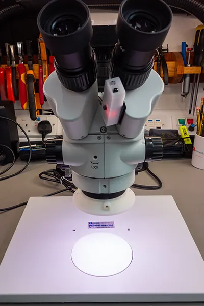
A few years ago, we invested in a new microscope to help with our electronics projects. Along with the microscope we bought an LED ring light to illuminate the subjects.
In 2021 we added a video camera to the microscope using a Raspberry Pi High-Quality Camera. The camera worked ok but we found one issue was the colour temperature of the ring light was very cold which meant any photos or videos we made came with a blue colour cast. This was especially evident on red or black PCBs where the LED colour made it difficult to get a good image.
To fix this problem we decided to design a new ring light using RGB LEDs. This would allow us to change the colour temperature to suit the subject that we are recording. Using programmable LEDs would also allow us to individually control each of the LEDs opening the door to adding new features like turning on a small segment of LEDs on one side to change the direction the light is coming from. This can be useful when looking at the text on integrated circuits as some text is only visible when lit from certain directions.
Before starting on the design, we came up with a set of features that we would like to build into the ring light.
- Adjustable brightness
- Adjustable colour temperature
- Adjustable light direction
- Controllable through a single rotary encoder
- Wi-Fi enabled with a web interface and API for external control
The Wi-Fi interface, while not essential, was one feature that we wanted to add as that would allow us to adjust the ring light from the computer when we are recording video. A web API would allow automation, for example turning the brightness up when taking a photo or video and then reducing it when we are not recording to save power.
Designing the hardware
The ring light is built around three circuit boards.
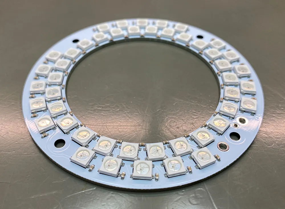
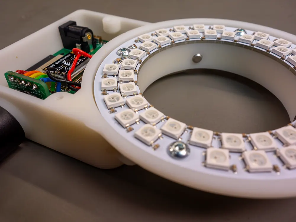
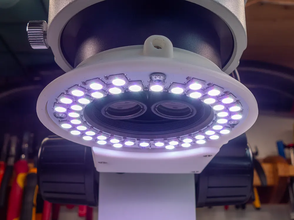
The first PCB contains the LED ring. We chose WS2812B programmable RGB LEDs as these are easy to control and can be wired in series. The diameter of the light was based around the size of the aluminium tube that was fitted to the microscope. The PCB has an internal diameter of 55mm and an external diameter of 84mm.
Two rows of LEDs were used, 26 LEDs on the inner row and 20 on the outer row to allow space for four mounting screws. This gave us 46 LEDs in total. Each LED needed a decoupling capacitor so to save space we used 0402 size 100nF capacitors. This made assembly fun as there were 96 components to place by hand on a small PCB.
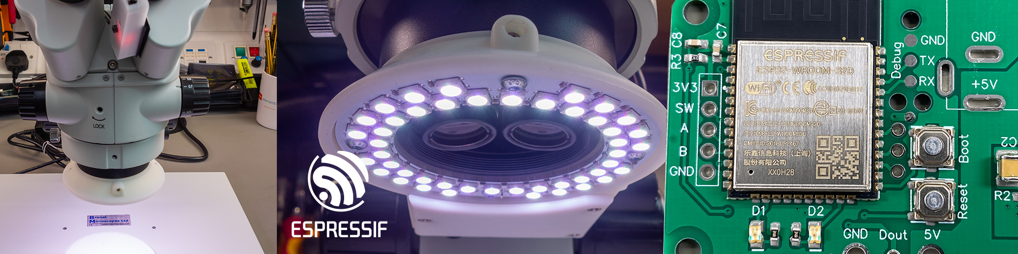
The second PCB contains the control circuit and a 3V voltage regulator. We used an ESP32 module to control the ring light. This gave us the Wi-Fi remote control that we wanted, and we have plenty of experience programming the ESP32 modules. An ESP32-WROOM-32D module was used as we already had several of these in stock.
The control PCB went through three revisions before we had one that worked properly.
The original idea was to use the power supply from our Elgato lights to power the ring light. This would save us from having to buy an additional power supply and let us use the same type of power supply for all our lighting. The Elgato power supplies run at 13V and the WS2812B LEDs use 5V, while the ESP32 module runs at 3V so we designed a dual switching step-down regulator around the TPS541620 from Texas Instruments. The TPS541620 is a dual 6A regulator that comes in a 25 pin VQFN package measuring 5mm x 3mm. The small size made it look like a good option as it would allow us to keep the PCB size small.
We designed the control board and ordered some PCBs from JLC PCB. When they arrived, we assembled the board and started testing it. It quickly became apparent that we would have a problem with heat management. Even though the step-down regulator is efficient it still generates heat and the small size of the regulator combined with the small PCB size meant that after a few minutes the temperature around the regulator went above 70°C. This would be a problem as we were planning on using a 3D printed enclosure and the maximum recommended temperature for the plastic was 60°C.
The first design was scrapped, and we moved onto revision 2. This would use a 5V power supply removing the need for one of the regulators and a linear regulator was used to drop the 5V to 3V for the ESP32 module, reducing the component count on the PCB. A LP3878MR-ADJ linear regulator was chosen as we already had several of these in stock. The ESP32 module, capacitors and switches were salvaged from the first board to be reused on the second board using a newly purchased hot plate.
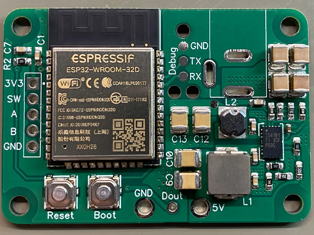
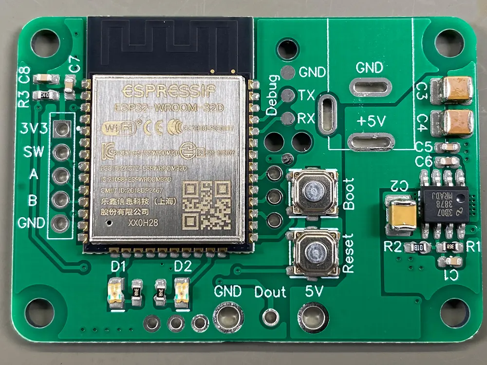
We added two status LEDs and three extra IO pins onto the PCB to give us room for expansion if needed. The plan is to use this control board for other LED projects in the future including a new light for our milling machine, so we tried to make it with these future needs in mind.
The PCB for the second revision was assembled and tested and it initially looked like everything would work but we quickly found we were getting communication problems with the LED ring. The ESP32 was running at 3V and the WS2812B LEDs run at 5V. We hoped that the digital inputs on the LEDs would work at 3V as there are plenty of ESP32 based WS2812B designs on the internet, and we had a prototype working with an ESP32 dev board, but our dev board runs at 3.3V and that 0.3V was enough difference that the WS2812B LEDs would not respond to the commands being sent to them.
To fix the problem we used a SN74AHCT1G125 buffer gate to level shift the output from the ESP32 to 5V. To save building another control PCB we used a SOT23 breakout board glued to the top of the ESP32 module for the SN74AHCT1G125 but the PCB that we have uploaded to our GitHub repository has the buffer included along with a few other minor fixes that were needed to the design.
The third PCB contains the rotary encoder and some debouncing resistors and capacitors. We used a separate PCB for the encoder as this allowed us to design a smaller enclosure that would fit in the space available on the microscope. If the encoder was soldered onto the control board it would have made assembly more difficult.
The Enclosure
The design for the enclosure was based around the constraints of our microscope.
We designed the PCBs for the ring light first and then imported models of the PCBs into the CAD software. A basic mock-up of the microscope was added so we could make sure our design would fit in the available space.
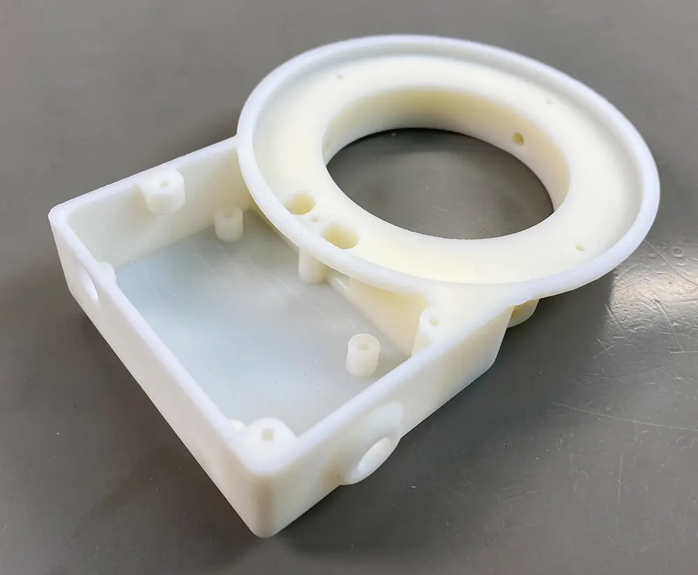
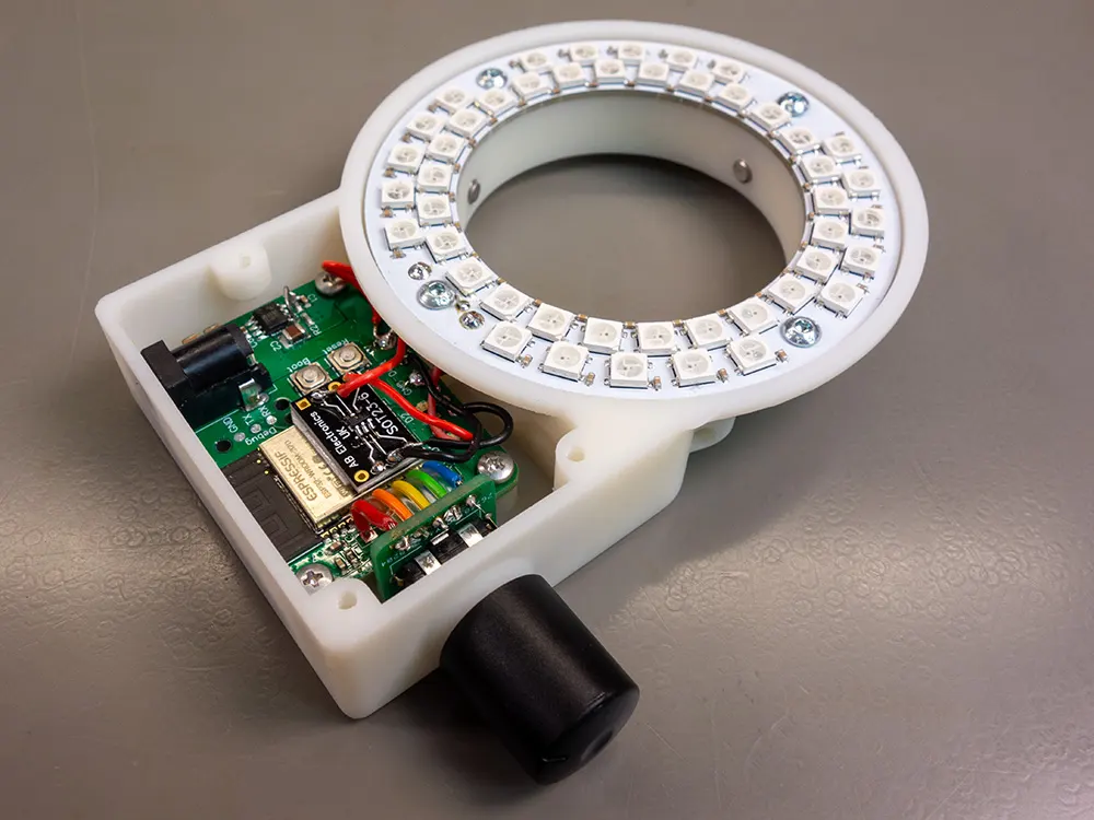
The PCBs were positioned in a way that would allow them to be connected with short cables and the enclosure was designed around the PCBs. We decided to use a 3D printed enclosure from JLC PCB using their SLA printers. This allowed us to design the enclosure in a way that would be difficult to do using our milling machine.
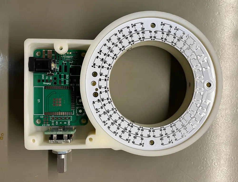
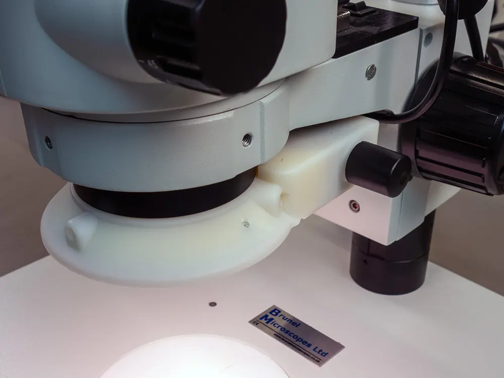
The LED ring is fitted to the enclosure using four M3 screws. The control board sits at the back with the rotary encoder alongside. Three short pieces of wire join the LED ring to the control board and a ribbon cable connects the control board to the rotary encoder. The back of the LED ring overlaps the control board so the pads for the three wires are almost aligned. This kept the enclosure small enough to fit below the microscope, but it did make assembly more difficult as the boards needed to be soldered together in position.
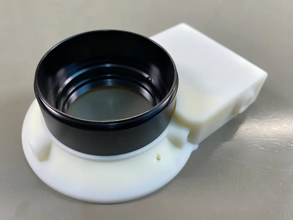
The enclosure fits to the microscope mounting ring using three M5 grub screws. All the holes in the enclosure were made undersized so that threads could be tapped into the plastic afterwards.
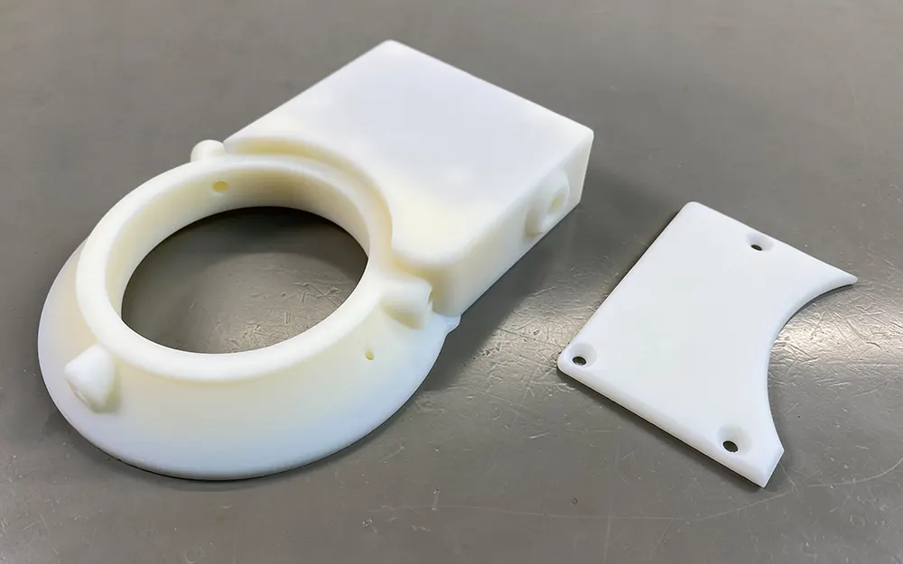
A small cover was also designed to cover up the control board. This is fitted to the main enclosure using three M3 screws.
With the enclosure designed we sent off the STL files to JLC PCB and waited for the parts to arrive. A couple weeks later the 3D printed enclosure arrived, and we assembled ring light. Everything went together without any problems.
The Firmware
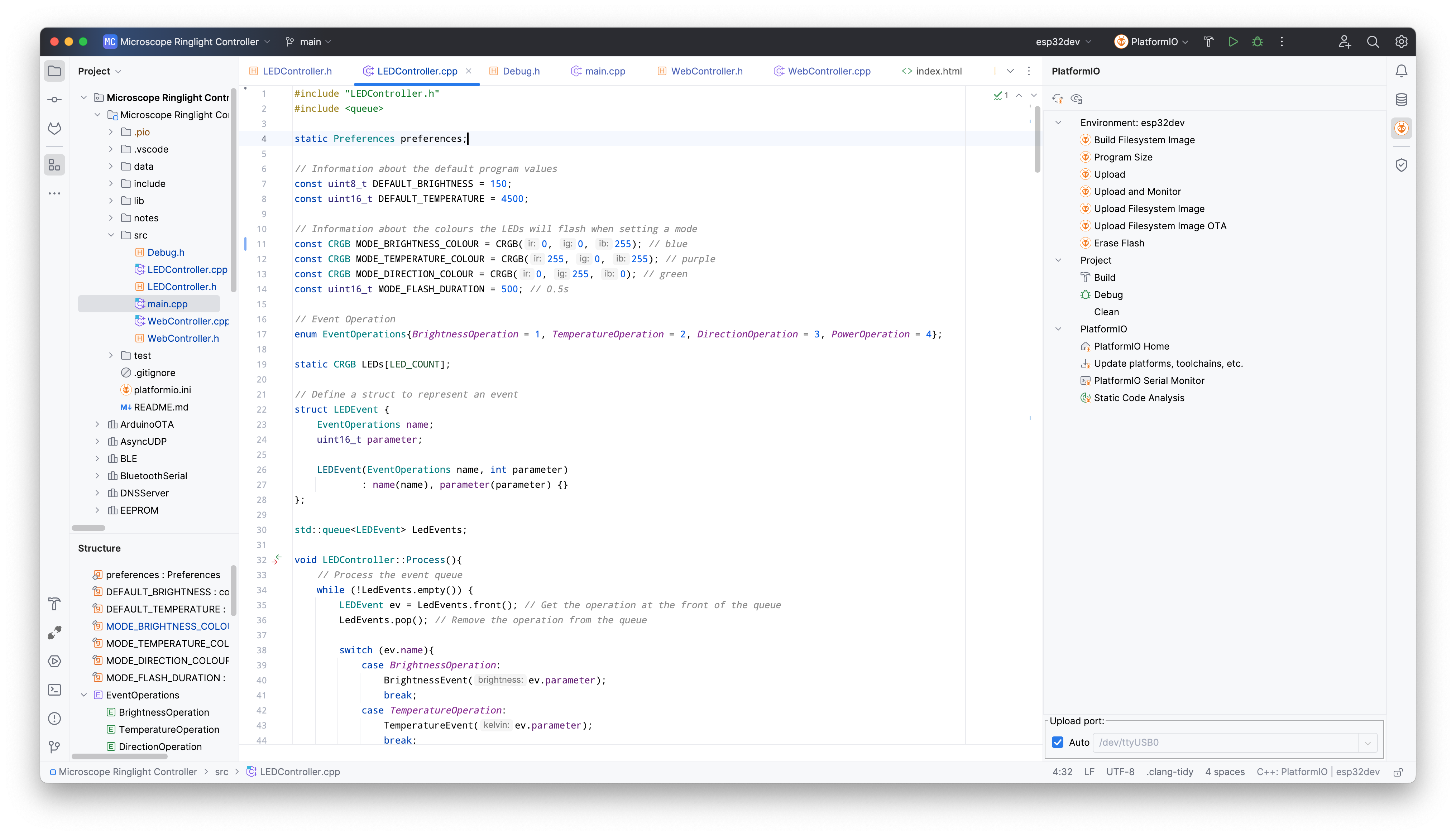
The firmware for the microscope ring light was developed in JetBrains CLion using PlatformIO and the Arduino framework. The files can be downloaded from Github at github.com/briandorey/ESP32-RGB-Microscope-LED-Ring-Light
For a long time, we have used Visual Studio Code for our development work. VS Code is a good IDE with plenty of extensions and it has served us well but a few months ago we came across the CLion IDE from JetBrains. We already use JetBrains Rider IDE for web development and after testing CLion for a while we found that the IDE is more polished than VS Code and the development experience is overall better and faster. CLion also is available for Mac OS, Windows and Linux which is useful as we use all three platforms for our development work.
The firmware allows control of the LED ring light through the rotary encoder on the side of the light or through an external web interface.
The ring light has three modes, brightness, colour temperature and LED direction. The mode can be changed by pressing the switch on the rotary encoder. When the switch is pressed the LED ring will flash blue, purple or green to show which mode it is in. If the ring light cannot connect to the Wi-Fi router it will flash red and disable the web interface. If this happens it can still be controlled locally.
Brightness Mode
In brightness mode turning the encoder clockwise increases the brightness and turning it counterclockwise decreases the brightness.
Temperature Mode
In temperature mode turning the encoder clockwise increases the temperature making the LEDs more cold or blue and turning it counterclockwise decreases the temperature making it warmer or more yellow.
Direction Mode
In direction mode most of the ring is turned off and a small segment of 9 LEDs is lit on one edge of the ring. Turning the encoder moves the position of the lit LEDs around the ring with 26 possible locations. This mode is useful when reading the labels on integrated circuits as the text is often more legible when lit from certain directions. When in direction mode the colour temperature is not used to increase the available light on the subject.
Web Interface
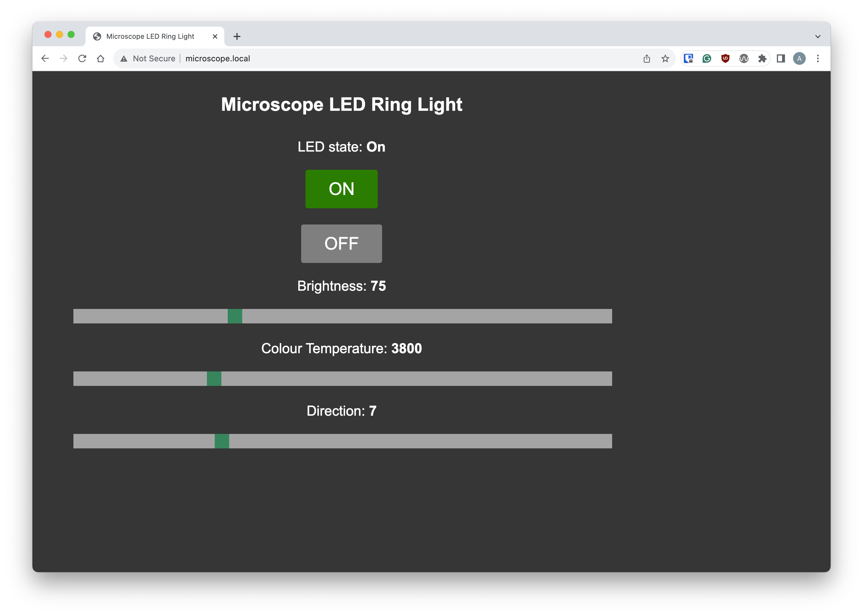
The web interface has a simple web page with two buttons for switching the LED ring on and off and three sliders for brightness, temperature, and direction. JSON is used for communicating with the web interface. We decided to use JSON as it would allow us to programmatically control the ring light with scripts or software like OBS.
The C++ Code
The program structure is not very complicated with the code split into three parts, the main program loop, an LED controller class, and a Web controller class.
The main.cpp file contains the code for initialising the hardware and enabling the Wi-Fi connection.
MDNS is used to allow web access through a domain name instead of an IP address. This makes it easier to access the ring light without having to set a fixed IP address.
Interrupts are used for the rotary encoder. When the encoder is rotated or pressed an interrupt occurs. A flag is set in the interrupt function, and this is then dealt with in the main program loop.
The LEDController class deals with all things related to the LED ring. The FastLED library is used for communicating with the WS2812B LEDs. This library has a range of useful features for controlling RGB LEDs.
The LEDController was initially designed with basic functions for controlling the power state, brightness, temperature, and direction. This worked well with the rotary encoder but when using the web interface which works asynchronously, we found that moving the sliders quickly would send commands to the LED ring faster than it could process them, effectively causing a denial-of-service attack.
To get around this problem we implemented a message que. When a new command from the rotary encoder or web interface is received it gets pushed into a queue. On each main program loop a process function is called which pops the command from the front of the queue and processes it. This fixed the DOS problem and allowed the web interface to work.
Web Interface API
The WebController class contains all code related to controlling the web interface. The HTML, CSS and JavaScript files are stored in a flash file system image and accessed using the SPIFFS library. You can find the files in the data/www directory.
The ESPAsyncWebServer library was used for the web server. Routes were added to serve the web page, style sheet and JavaScript as well as end points for the various JSON commands that control the ring light. The domain URL htttp://microscope.local was chosen for the ring light.
Calling the URL http://microscope.local/getstate returns the following JSON string.
{"numberOfLights":26,"lights":[{"on":1,"brightness":11,"temperature":2770,"direction":0}]}
numberOfLights: The number of positions for the LED direction slider.
on: The power state for the LED ring light, 1 = on, 0 = off.
brightness The LED brightness, 0 to 255.
temperature The LED temperature in kelvin, 1000 to 12000.
direction: The LED direction, 1 to 26. 0 will turn on all LEDs.
The web page calls /getstate every 2 seconds to keep the slider positions updated in case any changes are made using the rotary encoder.
The following endpoints are used to control the ring light.
/power
/brightness
/temperature
/direction
Posting a JSON string to each of these URLs will call the corresponding function in the LED controller.
For example, if the following string is posted to /brightness it will set the LED brightness to 128.
{
    "brightness": 128
}
You can download the hardware files and firmware for the microscope from our GitHub repository.
The video below shows the LED ring light in operation.
All Espressif's logos are trademarks of Espressif Systems (Shanghai) Co., Ltd.
Comments