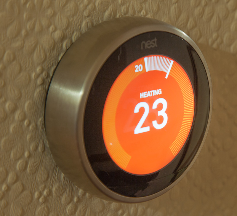
Today the new 3rd Gen Nest Learning Thermostat with hot water control arrived which we had ordered last month when the new UK model with hot water control was announced.
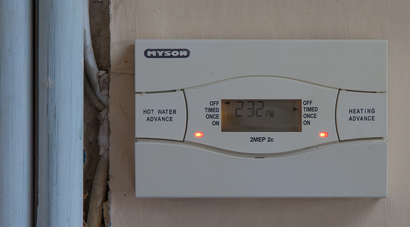
We needed the Nest Thermostat with the hot water control to replace our old Myson two-channel timer which we had been using for many years to control the central heating and hot water.
We wanted to be able to have more control over the heating and hot water in the house and also wanted to remotely control the hot water when out walking with the dogs. They sometimes roll in fox or badger mess and get very smelly and so being able to get back home to have hot water ready to shower them off would be a big advantage.
There are other remote access systems available in the United Kingdom but they nearly all needed to be installed by a “professional” and would only be connected to a modern boiler. As our gas boiler is over 50 years old we didn’t think they would set everything up as the boiler doesn’t have all the “modern” features, but has lasted a lot longer than any modern boiler our friends have had installed in their homes which seem to need to be fixed very often or replaced every few years which didn’t seem to be very efficient when you add the cost of a new boiler into the annual running costs!
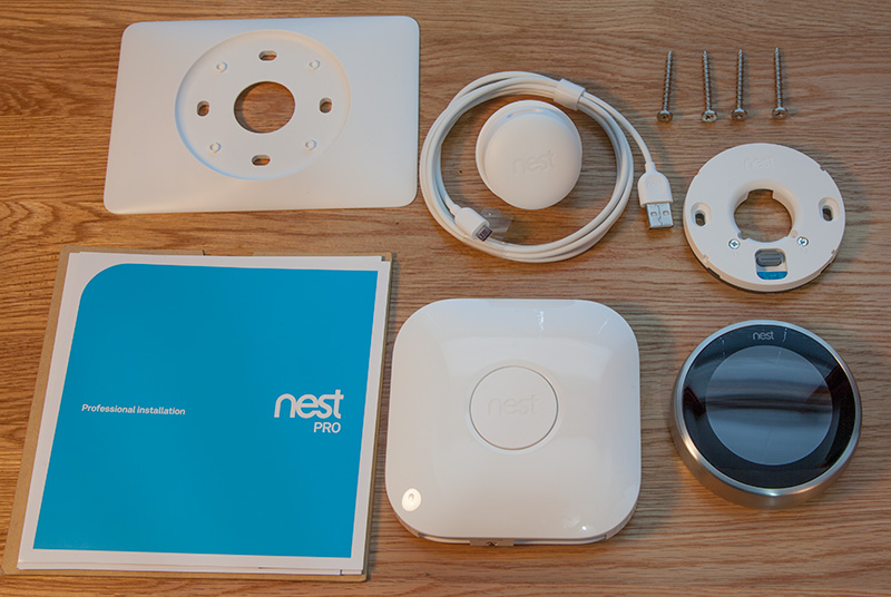
Upon opening the box, we found the following items:
- Instructions and basic user guide
- Nest thermostat
- Nest Heat Link
- Thermostat wall bracket
- Thermostat's flat plastic surround
- USB cable and mains 5V adapter
- 4 Screws
We decided to install the thermostat on our upstairs landing and the old central heating controller was installed in our Kitchen downstairs and so we had to run a two-core cable from the old controller to the location of the new Nest Thermostat upstairs to power the thermostat controller without having to use the mains plug in supply.


With the PCB built the last thing to do was make the case. We had some old sheets of Delrin and acrylic sheets left over from previous projects so a case was designed in Adobe Illustrator and cut on the mill. The base is machined out so the PCB bolts down in several places and the Raspberry Pi ports are recessed into the right side. The sides of the box are made up of six layers of acrylic cut to allow all of the connectors to be accessible and shield the 240V part of the circuit. The top and bottom of the case were left open to allow air to flow up through the Raspberry Pi keeping it cool. A clear lid was cut for the top and secured in place with two bolts.

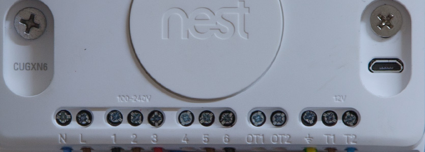
The thermostat mount has a small spirit level built into the base and so this made it very easy to align the mount on the wall and keep it upright. The 12V supply cables were installed into the T1 and T2 screw terminals and the thermostat was clipped onto the mount on the wall.
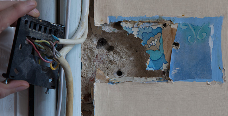
In the Kitchen, we unscrewed the cover of the old controller and found that a section of the plaster was missing where the cables fed into the back of the controller mount. We attached small labels to each of the cables so we knew where they needed to be connected to and then removed the old controller's wall bracket.
The Nest Heat Link box has cable access clamps and space at the bottom of the unit but as all our cables come from behind the controller in the wall we felt it would be a lot tidier and safer to have the cables come into the back of the Heat Link box. We carefully cut a pair of slots in the back of the cable area and we were then able to feed the cables from behind the Heat Link box was fitted to the wall with two screws and wall plugs.
The supplied screws are not very long and would be ok if you are fitting the boxes to wooden walls but as we needed to drill and use wall plugs we needed to find longer screws for the Heat Link box. The walls in the kitchen are made of stone and are held together with lime mortar which is over 100 years old. One hole went into a gap between the stones and we had to glue the plastic wall plug into the hole with PVA glue as the lime plaster doesn’t hold very well with wall plugs, the other mounting hole went into one of the stones which took around 10 minutes to drill to approx. 60mm deep and took several steps with different drill sizes!
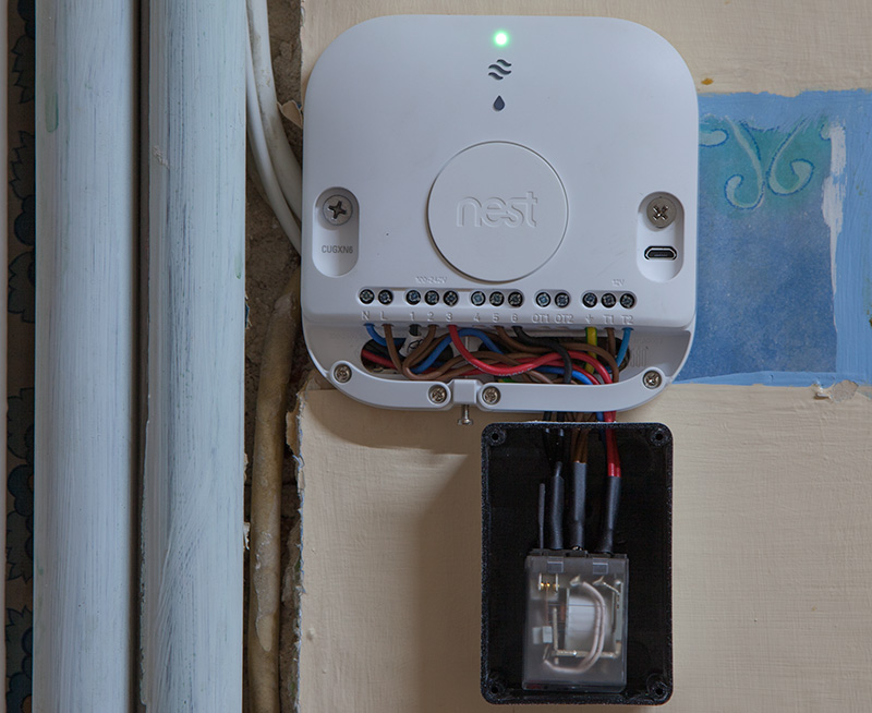
Once we had connected the cables back into the Heat Link connectors we found that our previous central heating controller was configured to supply power to the hot water circuit when the central heating was enabled and the relay control on the central heating side was only used to control a two-way water valve which redirects the hot water from the boiler to either the radiators and hot water tank or directly to the tank if the central heating is on its normally closed contact.
The Nest Thermostat doesn’t have the facility to turn on the hot water relay when the central heating is activated and so we needed to find a workaround to supply power to the hot water cable when the central heating output is enabled but also being isolated from the hot water output when the central heating is not needed and we only need to heat the water tank.
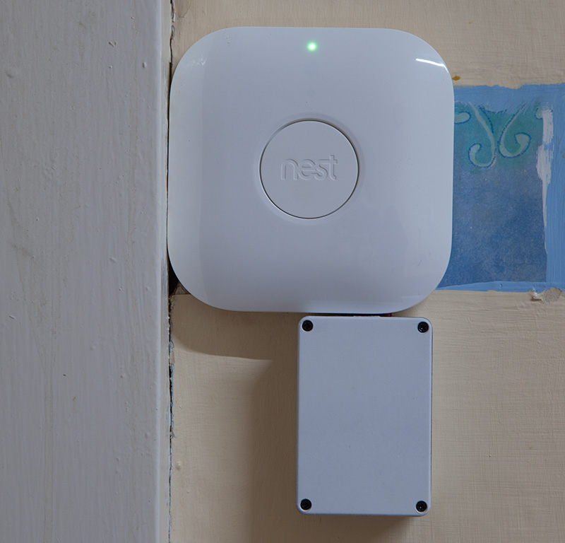
We resolved this problem by adding an additional mains-powered relay to supply power to the hot water wire when the central heating relay in the Heat Link is activated. We purchased a mains relay from Maplin Electronics and a small plastic box which we fitted to the wall below the Heat Link box. An alternative workaround for this is shown in the comments below which uses the internal relays to do the same function.
We fed the wires from the relay box into the lower cable entry on the Heat Link (see photos) and when the cover is on the Heat Link the cables are not visible. We will paint the relay box to match the walls to make it less visible.
After setting up the Nest Thermostat and connecting it to our wifi network we added the Nest apps to our iPads and iPhones and the remote access and interface appear very easy to use.
Overall the installation went without any problems apart from needing the additional relay to work with our older boiler. I felt that the Heat Link would have been better if the back of the cable entry area had the slots already installed in the case so you have the option to install the cables from below or behind.
Also, the wire clamps are small and it isn’t possible to install more than one cable at a time and so linking the mains live cable to the centre relay contacts meant that we needed to join the cables in a separate connection block behind the unit in the wall. Having slightly larger wire clamps or maybe even adding cable jumpers into the back of the box to link the mains live to the relay centre contacts would have made the installation simpler.
Nest are talking about releasing internal API access to the thermostat controller which means that we can then use our Raspberry Pi data logger to communicate with the thermostat and so we can then set the hot water heating times to be set based on the current hot water tank temperature.
Update 22/02/2018
Due to the changes to the comments system, I have created an archive of all previous comments including pictures as a PDF file.
Mark C
Hey Brian, nice solution with the extra relay but I think it was unnecessary. What you have behind points 4,5,6 is a simple relay anyway.
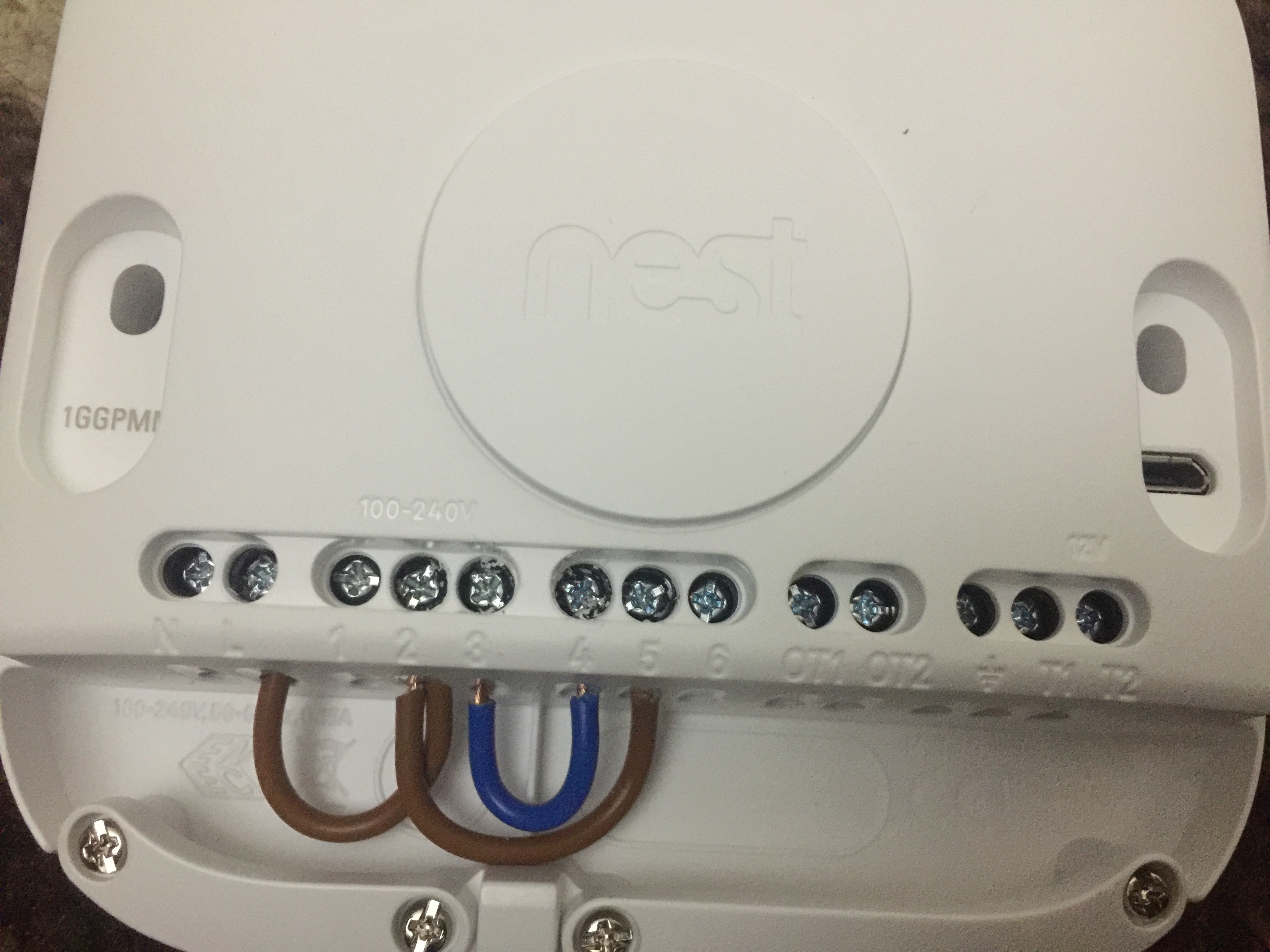
So, all you had to do was jumper 3 (CH ON) to 4, connect live to 6 and have (HW ON) fed off 5.
Turn on CH it also passes current to 4/5 which is "Normally ON" so kicks in the HW. Turn on "JUST" HW it bridges just 5 & 6 (4 & 5 are no longer bridged so no current to CH) Simples :-)
Waddy
Hello just found your post while searching for problem. Installed Nest 3rd Gen. All works well when heating on but concerned about hot water. I have oil boiler y plan system hot water tank is open ( filled with header tank) if I press boost on phone app for water only boiler fires up then stops immediately. Can I work around this and if heating gets to required temp does that mean my hot water won't heat??? Help would be appreciated.
brian
Hello Waddy, Do you have a make and model for the boiler which you can post? It could be a thermostat in the hot water tank shutting the boiler off.
andrew freeman
hi,i have been asked to fit nest room stat to a 3 zone heating system.do I need 3 room stats to do each zone of the house(upstairs,downstairs and extension underfloor).it also has hot water cylinder.
Nik
Great article, thanks for taking the time to write and publish it.
Would you mind telling me where you bought the relay, as I am looking to do a similar installation. Most of the relays I have found are huge and unsightly!
Brian
I got the relay from https://uk.farnell.com/ and most suppliers will have a suitable relay.
Paul
Before anyone goes down the route of adding a relay - check out the previous comment in the above PDF by Mark C. The nest does all this for you, all you need to do is wire it correctly by just adding a couple of jumper wires. .... It worked for me , no relay necessary.
Paul
Before anyone goes down the route of adding a relay - check out the previous comment in the above PDF by Mark C. The nest does all this for you, all you need to do is wire it correctly by just adding a couple of jumper wires. .... It worked for me , no relay necessary.
AMUR VOSKANYAN
Thank you for a very good explanation. My question is a little different.
There is a double-circuit gas boiler company Solly. From the boiler wire goes to connect the thermostat. The fact is that the heating mode in all boilers works when these wires are closed, but I have the opposite situation. The heating works when the wires are opened. When closed, the heating is turned off, that is, the boiler turns off the burner. I read in all forums that these boilers work according to the normally open relay mode.
The question is, what contacts heat link to connect my wires. There are contacts 1, 2, 3 and I see that everyone is connected to pins 2 and 3, since for all the heating operation mode works when the contacts are closed. What do i do? If I connect to pins 1 and 3, will it be correct?
Keith
Thanks for the work around for the HW, works great. I have have another zone that I want to add the nest to also. Im trying to figure out how to wire the second heat link so when heat is need upstairs it will call for hot water and open the value to the radiators upstairs without powering the value downstairs. Can it be done without adding a relay?
Renaldas
Hi,
I have gas boiler and hot water cylinder, which is system-s I believe. Can I still use the wiring scheme in the picture that Mark C. uploaded?
Thanks
Brian
Renaldas, I think it should work ok
tomski
have anybody received nest box without power supply or cble?
Sarah
Hi, i have looked all over for answer to my issue and you seem the most clued up to help.
I am in no way technical but if you could give me a little hint to stop me going crazy.
I moved into this house in August and it had nest installed, i have always had a combi boiler in the past but this house has a tank.
Now, the nest works great over winter with the heating and hot water schedules kicking in when they should however, i know have a issue now its summer and i want to turn my heating off. If i turn the heating off and leave the hot water schedule as it was, the schedule does turn on the water when it should, i say turn on, it says on when i look at the app or the thermostat but its not actually heating the water.
it wont start heating the water unless i have the heating on and crank it up to kick in i.e put the radiators on.
i tried keeping the heating on but turning it way down but still the hot water doesn't actually start heating until the boiler fires up to turn the radiators on, i have to out the thermostat up to 20 for this to happen. i guess i could go and turn my all my radiators off but i would have thought something like this would still heat water without having to have the actual heating on..
i may be being dumb but any pointers would be great as nest arent taking phone calls at the moment.
Thanks so much
Colm
Hi, I have two earlier gen Nest thermostats connected to heating zones and I recently purchased the 3rd gen Nest for a third heating zone. Boiler has always been on 24/7 as it heats the HW cylinder. I was hoping to use the new Nest to also control the boiler and be able to switch it on and off remotely using the second set of terminals (4,5 & 6) but I cannot see how this can be achieved in terms of the wiring or indeed how the app might work in that regard. Thanks in advance for any guidance.
Gar D
Great info guys. Mark Cs image is a bit misleading because you have the live loop in input 5 not 6. The text is correct but the image is not. Hope that helps.
Mark Fenwick
Gar D, I don't believe the words are accurate either. Why would you connect Live to HW on (6)?
Richard
Hello- I had a plumber/electrician come over to install the 3rd gen google nest. The problem I have is that when I wanted to boost the hot water for 30min/1hour/2hours it turns on the central radiator heating. When i want to turn on the central radiator heating it doesn't work and i believe the hot water boiling system turns on. It it totally opposite functioning. - Any help thanks
Zsolt
Hi, I have a system boiler with hot water tank and x2 zone valves switching between hot water and heating. Is there any instruction about how can I wire these up? I want to remove my salus controller but cannot find any thermostat that can control my system. Cheers
Neil
These posts saved me a lot of messing about. Cheers Brian and Mark-C for this much love
Luka S
Hi, would these solutions work for a Nest 3rd gen system with heating already connected to an electric boiler, and a separate HW cylinder with immersion heaters that I want to control through Nest? HW is currently connected to just a switch on the wall. Thanks
Mary
Hello. Thank you for your detailed article. I’m hoping you can help me with my Nest installation.
I have a Danfoss TP9000 but the wiring on mine looks different. I have three brown wires attached to L. Can I attach these to the Heat Link (in L, 2 and 5) instead of installing jumper cables?
Also, in the Danfoss, I have a cable in 5 and 6 which I believe is for the remote sensor. Where should I be putting these? I can’t see a place for them in the Heat Link.
Brian
Hi, I found this page which may help with wiring your heating controller to the nest
http://www.aimlesswandering.uk/web/2016/02/new-house-old-tech-replacing-a-danfoss-tp9000-with-a-nest-3rd-gen/
Mary
Hello. Thank you for your detailed article. I’m hoping you can help me with my Nest installation.
I have a Danfoss TP9000 but the wiring on mine looks different. I have three brown wires attached to L. Can I attach these to the Heat Link (in L, 2 and 5) instead of installing jumper cables?
Also, in the Danfoss, I have a cable in 5 and 6 which I believe is for the remote sensor. Where should I be putting these? I can’t see a place for them in the Heat Link.
Mary Leigh
What did you use to cut wire access holes in the heat link backplate? This is what I want to do but am concerned about breaking my expensive new toy!!
Brian
I used a small drill to make the holes in the plastic.